
Flow sensor and strainer integrated flowmeter

a flow sensor and strainer technology, applied in the direction of liquid/fluent solid measurement, volume metering, instruments, etc., can solve the problems of vain dissipation of kerosene energy held by the kerosene, insufficient suppression of the variation of the flow-rate measurement value, and difficulty in accurately measuring the flow rate of fluid

Inactive Publication Date: 2003-08-12
MITSUI MINING & SMELTING CO LTD
View PDF9 Cites 18 Cited by
  • Summary
  • Abstract
  • Description
  • Claims
  • Application Information

AI Technical Summary

Benefits of technology

Further, an object of the present invention is to provide a flow rate sensor which can accurately measure the flow rate of the viscous fluid flowing in a pipe line under a broad environmental temperature condition on the basis of lowering the temperature dependence of the detected flow rate value.

Problems solved by technology

As described above, the conventional flow rate sensor has such a problem that it is difficult to measure the flow rate of fluid accurately when the fluid is viscous fluid.
Even when fluid has low viscosity at room temperature, it induces a problem connected to the above viscosity problem because the viscosity of the fluid increases as the temperature is lowered.
However, it is insufficient for suppressing the variation of the flow-rate measurement value due to the temperature of the fluid.
Further, since kerosene is incompletely burned (combusted), the energy held by the kerosene is vainly dissipated to produce incomplete combustion gas such as carbon monoxide or the like, which causes air pollution.
If the foregn matters are fixed to and accummulated on the fin plate of the sensor, an area of the fin plate used for heat conduction is reduced and a detail of the kerosene flow around the fin plate is changed to thereby cause significant lowering of the detection accuracy of the flowmeter.
According to the air fuel ratio control method, the incomplete combustion can be prevented, however, the reduction of the heating value produced in the boiler 301 cannot be prevented.
However, in the conventional flowmeter 408, an operator cannot recognize the flow rate of the kerosene directly so that the operation al work of removing the foreign matters from the inside of the nozzle 409 cannot be conducted immediately.

Method used


Image

  • Flow sensor and strainer integrated flowmeter
  • Flow sensor and strainer integrated flowmeter
  • Flow sensor and strainer integrated flowmeter

Examples


Embodiment Construction

Embodiments of the present invention will be described with reference to the drawings.

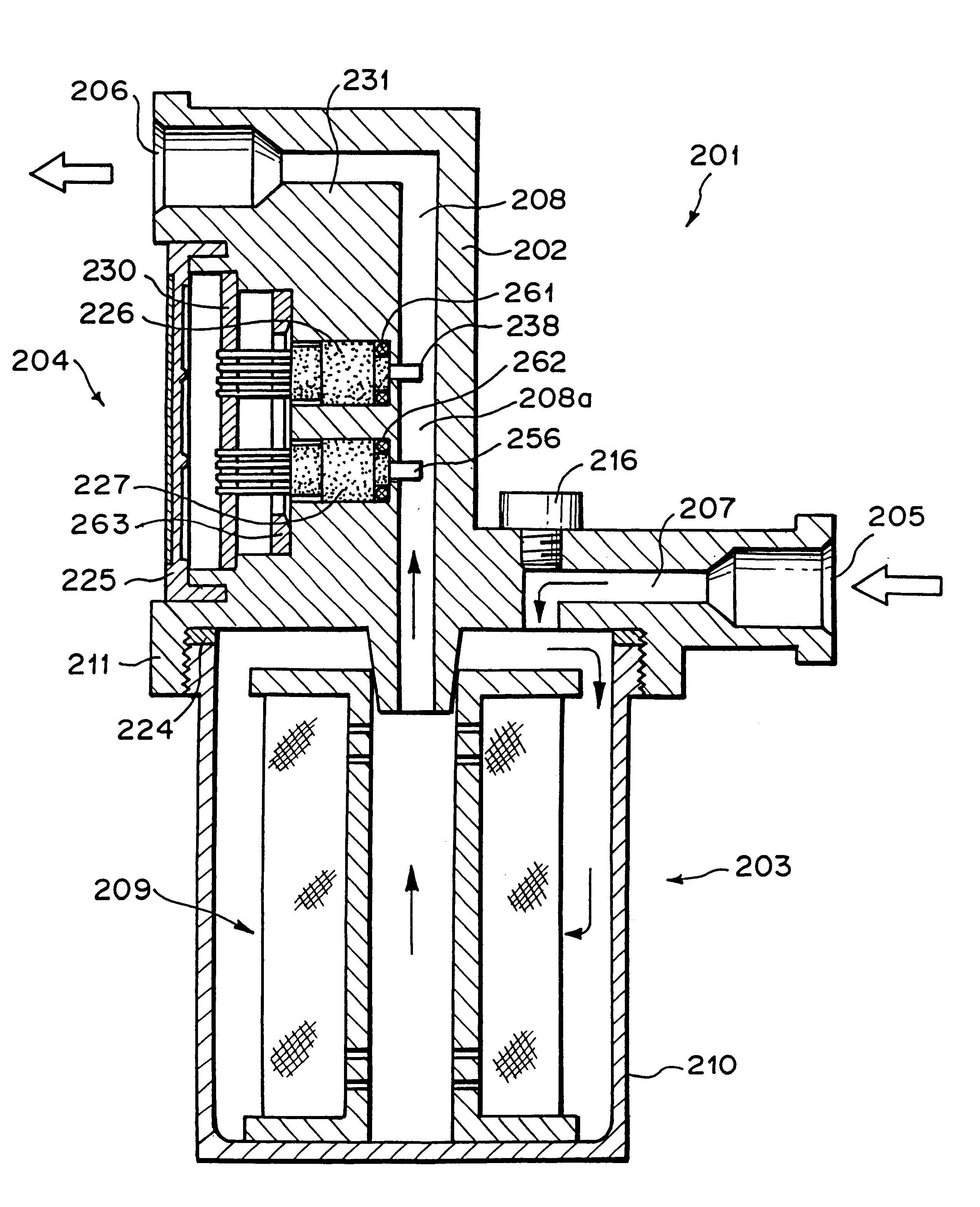
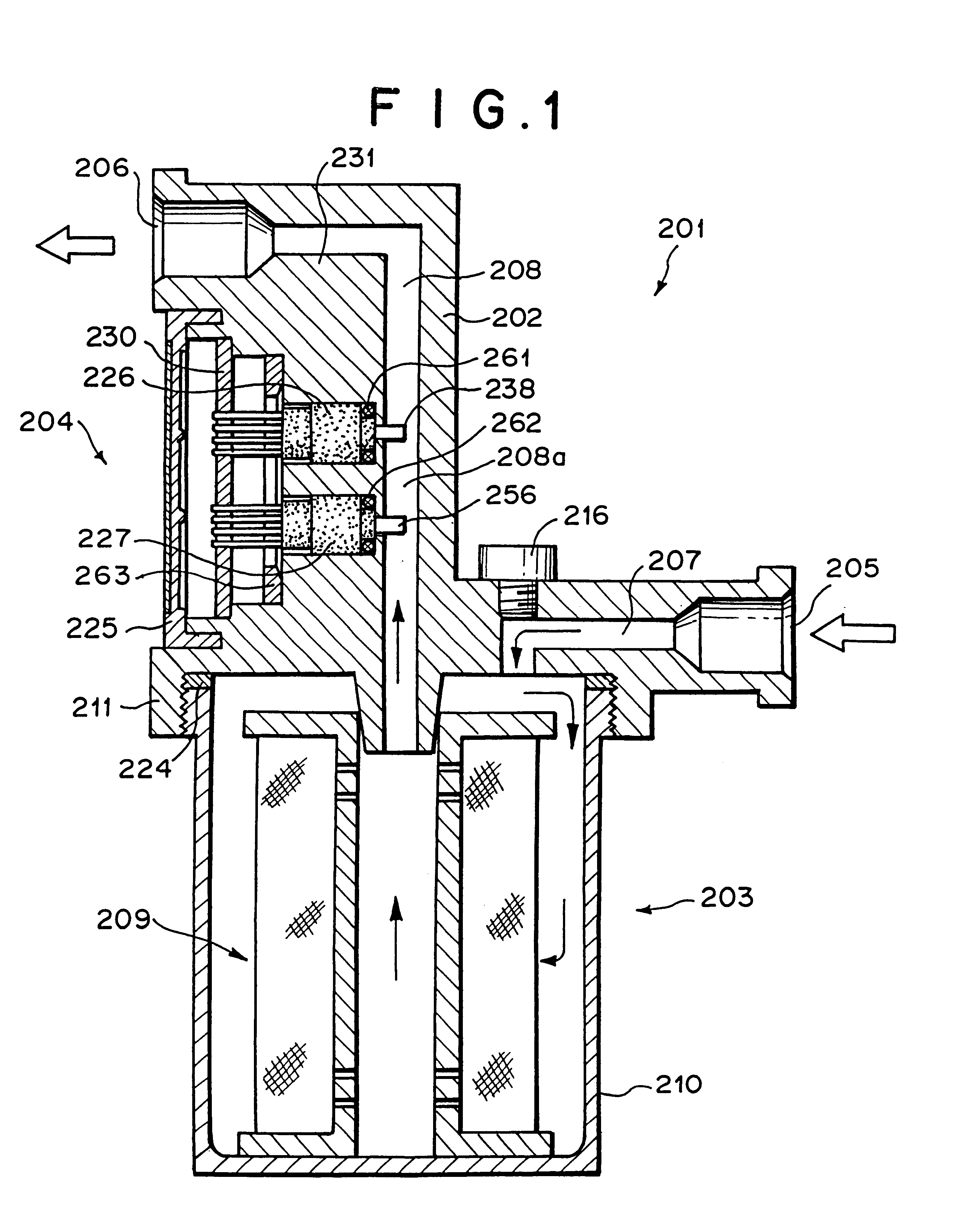
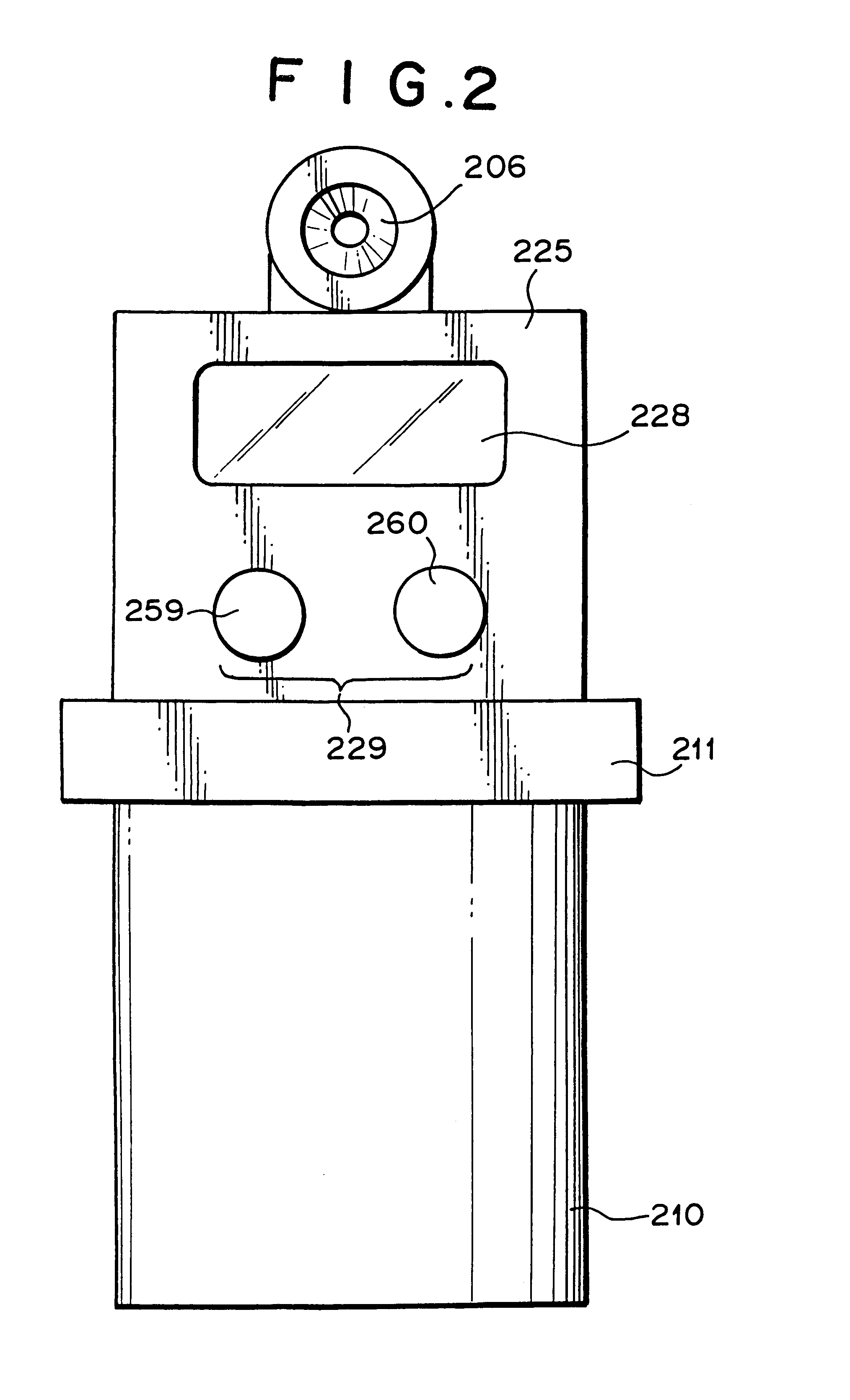
FIGS. 1 to 3 show an embodiment of a strainer integrated flowmeter according to the present invention. As shown in these figures, a strainer section 203 and a flowmeter section 204 are integrated to each other so as to share a housing 202 with each other.

The housing 202 is manufactured by casting (die casting) of aluminum, zinc, tin alloy, etc. Both the end portions of the housing 202 are designed as connection portions 205, 206 for connecting the external pipe lines, and an inflow side flow passage 207 and outflow side flow passage 208 are provided in the housing 202.

The strainer section 203 comprises a lower half portion of the housing 202, filter member 209 and filter member insertion cylinder 210.

On the half portion of the housing 202, there is formed a cylinder connectiong portion 211 slightly protruding downwards. A connecting recess portion 212 is formed At the inside of the cylinder connect...


PUM


Abstract

A strainer integrated flowmeter 210 is constituted by a strainer section 203 provided with a housing 202 having a flow passage 207 formed therein, a filter member 209 and a filter member insertion cylinder 210; and a flowmeter section 204 provided with a housing 202 having a flow passage 208 formed therein and a flow rate sensor 226. The housings 202 of both the strainer section 203 and flowmeter section 204 are integrated, and the flowmeter section 204 is disposed at downstream side. A vent hole 215 is formed in the housing 202 so as to be in communication with the flow passage 207.

Description

(1) Field of the InventionThe present invention belongs to a fluid flow rate detection technology, and particularly relates to a flow rate sensor for detecting the flow rate of fluid flowing in a pipe line. The present invention intends to enhance the detecting accuracy of the flow rate sensor.Further, the present invention relates to a strainer-integrated portable flowmeter which can be mounted on a pipe line through which kerosene is supplied to a kerosene burning apparatus such as a stove, boiler or the like to measure the flow rate of kerosene while removing a foreign matters such as dust or the like.(2) Description of the Related ArtVarious types of sensors have been hitherto used as a flow rate sensor (or flow velocity sensor) for measuring the flow rate (or flow velocity) of various fluid, particularly liquid, and a so-called thermal (particularly indirectly heated type) flow rate sensor is used because the cost can be easily reduced.A sensor in which a thin-film heating elem...

Claims


Application Information

Patent Timeline
IPC IPC(8): G01F1/699G01F1/696G01F1/684G01F15/08G01F15/00G01F15/12
CPCG01F1/684G01F1/6842G01F1/699G01F15/08G01F15/12H01L2224/48091H01L2924/181H01L2224/48247H01L2224/73215H01L2224/32245H01L2224/4826H01L2924/00014H01L2924/00012
Inventor KOIKE, ATSUSHIYAMAGISHI, KIYOSHIHIRAIZUMI, KENICHITAKAHATA, TAKAYUKI
Owner MITSUI MINING & SMELTING CO LTD
Learn More