Planar metallized substrate with embedded camber control material and method thereof

a technology of camber control and metallized substrate, which is applied in the direction of transportation and packaging, other domestic articles, natural mineral layered products, etc., can solve the problems of reducing furnace capacity, electrical shorting or opening in the final assembled module, and significant increase in product cost, so as to reduce the effort and eliminate any processing differences

Inactive Publication Date: 2001-09-04
GLOBALFOUNDRIES INC
View PDF14 Cites 21 Cited by
  • Summary
  • Abstract
  • Description
  • Claims
  • Application Information

AI Technical Summary

Benefits of technology

Yet another purpose of this invention is to manufacture thin and small ceramic substrates with low flatness.
Still yet another purpose of this invention to provide a process which minimizes the cost of sintering such thin and small ceramic packages and requires no flattening.
Also shown in FIG. 1 is a voltage plane 29 and one ground plane 19. The voltage plane 29, in layer 22, provides power to the electronic device 10 through the vertical metal line 23 and the connecting solder ball 15. The voltage plane 29, in layer 22, also provides a horizontal translation to the vertical voltage line 23 to connect to the solder ball 35, which is electrically connected to a board (not shown). Voltage planes typically have uniformly distributed metallurgy covering between about 30 percent and about 80 percent of the ceramic area available in such layers. Large area coverage typically indicates a layer with solid metal coverage and very limited areas with exposed ceramic. Low area coverage is typically seen in voltage planes designed using a mesh-like metal pattern. A typical ceramic substrate 20 which includes voltage planes will have at minimum two of such planes with nearly identical metal coverage, where one plane is used to supply the voltage and power to the electronic device and the other voltage plane provides the electrical ground connection. Nearly identical voltage planes are standard in electronic substrates 20, because they minimize the design engineering effort to create them. However, for some applications an additional voltage plane may be required if the electronic device 10 needs two different voltage supplies to operate. Typically, these voltage planes are metallized using the same metal paste formulation, mainly to reduce manufacturing costs.
For a given voltage plane designed with the minimum required area coverage, for example about 20 percent, the designer can easily increase the metal covered area by about 10 percent to about 30 percent if needed. Only lower increases are possible when the area covered initially is high. In that case, an alternative method to increase the amount of metal in a given voltage plane, without significant change in the area covered by the metal, is to deposit a metal layer of higher thickness over the ceramic layer during the layer fabrication step prior to sintering. This method is easily applicable to the existing processes used to deposit thick metal films over ceramic layers but requires the expense of retooling some of the line components; thus it should be used sparingly.
Using the method of this invention one can evaluate and define an accurate design modification for a given thin and small MLC substrate to eliminate the need for substrate flattening to control camber and via bulge. This could be done by evaluating the initial design with two different metal pastes on the voltage planes as described previously, and then adjusting the metal volume coverage of one or more of the voltage planes or other metal plane according the method. Of course, a similar procedure would be used when the same metal material is used in the different voltage planes.
The method of this invention reduces the efforts needed to produce a flat thin and small substrate which requires no flattening. This can be done by selecting one or more of the following substrate design recommendations, such as, (a) matching the thickness of the top and the bottom layers, and / or (b) eliminating any processing differences between the top and bottom ceramic layers when selecting the ceramic layers before sintering.

Problems solved by technology

If the ceramic package is not sufficiently flat after sintering, it needs to be discarded or reworked, and in both cases the product cost is increased significantly, because of the relatively high rework cost; the increased need to characterize the product; and / or the replacement cost associated with discarded product.
A large camber at the bottom of the package or high via bulge at the top will result in electrical shorts or opens in the final assembled module.
However, as the package becomes small and thin and the integrated circuit chip becomes large, a larger fraction of the substrate camber becomes the package via bulge because in thin products the package top surface mimics the bottom surface.
In both methods, the use of weights reduces the furnace capacity and increases the furnace thermal load; therefore, the sintering cost is increased when compared to the cost of sintering the same substrates without weights.
Unfortunately, the use of a CTE gradient is only practical when mechanical properties of the package are suitable for such effect, like plastic or metal assemblies with low elastic modules.
Ceramic packages, which have high elastic modules, will not bend sufficiently when using the Burns methods to compensate for camber problems.
Attempts to reduce the difference in shrinkage rate differential between the ceramic and the metal have not been successfull because of the intrinsic different nature of the materials being co-sintered.
But, the metal distribution balancing effort becomes more difficult as the number of layers used to build the ceramic package decreases.

Method used


Image

  • Planar metallized substrate with embedded camber control material and method thereof
  • Planar metallized substrate with embedded camber control material and method thereof
  • Planar metallized substrate with embedded camber control material and method thereof

Examples


example 1

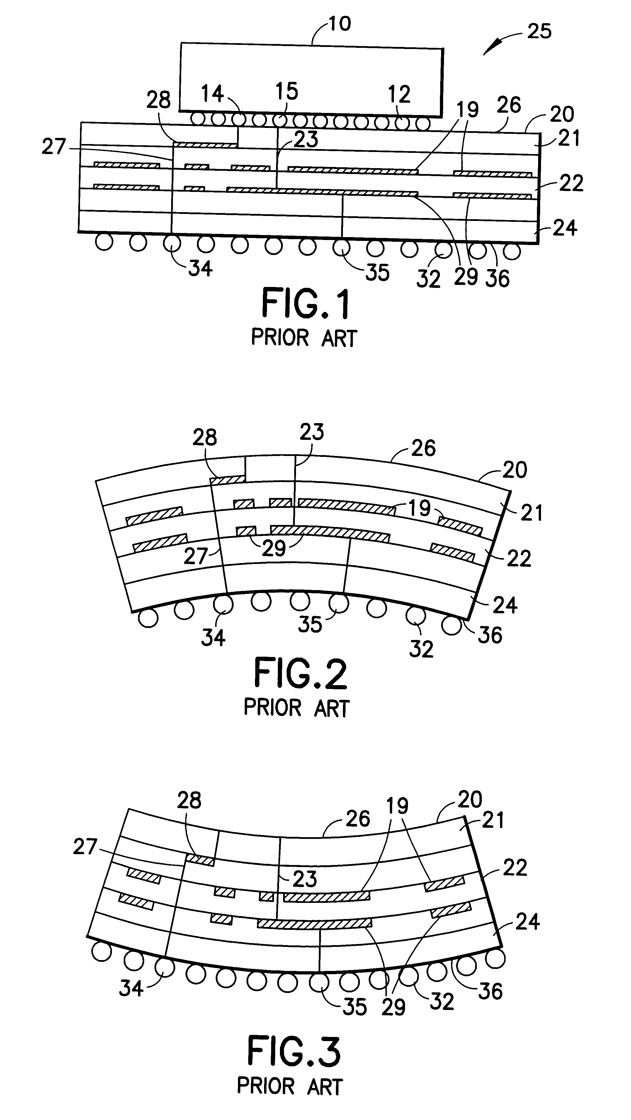
This is a particular example of a camber and / or bulge as shown in FIG. 2, where the surface profile of a typical substrate after sintering was measured using a surface profilometer. It was found that the via bulge was about 40 microns on the vertical axis, and the total camber was over 80 microns. This via bulge was found to be unacceptable, and rework to produce a flat planar ceramic substrate was now needed on this ceramic substrate. After rework, the surface profile of the reworked substrate was measured which showed an acceptable via bulge of only about 15 microns on the same horizontal axis range used to determine the via bulge before rework.

example 2

A flat thin electronic ceramic substrate 20 was prepared, where the ceramic substrate 20 design had at least two internal voltage planes, as shown in FIG. 5. The voltage plane near the top surface of the substrate 20 was screened with a metal paste which had produced the largest camber in one of the metal layer test vehicles. The second voltage plane that is farthest from the previous voltage plane was screened with a metal paste which had produced the lowest camber in a one layer test vehicle. In addition, the metal paste volume on the top voltage plane was then modified by the addition of at least 5 percent metal paste volume to produce a multi-layer ceramic substrate that had via bulge below about 15 microns and total camber less than about 50 microns.


PUM

PropertyMeasurementUnit
Lengthaaaaaaaaaa
Lengthaaaaaaaaaa
Fractionaaaaaaaaaa

Abstract

The present invention relates generally to new planar substrates that are metallized and embedded with material to minimize the camber and method thereof. The invention also relates to the fabrication of multilayer ceramic (MLC) substrates for packaging electronic devices. More particularly, this invention relates to the fabrication of thin and small ceramic substrates which do not need post-sintering processing to control the flatness of the sintered product.

Description

The present invention relates generally to new planar substrates that are metallized and embedded with material to minimize the camber and method thereof The invention also relates to the fabrication of multilayer ceramic (MLC) substrates for packaging electronic devices. More particularly, this invention relates to the fabrication of thin and small ceramic packages which do not need post-sintering processing to control the flatness of the sintered product.Ceramic packages are needed by the electronic industry to provide a required level of electrical interconnection between an electronic device, such as, a chip, and a board, such as, a plastic board.The ceramic substrates have the ability to provide a high density interconnection surface on the top layer which connects to the integrated circuit chip and a lower density interconnection surface on the bottom layer which connects to the board. This interconnection density is particularly high when flip-chip solder balls, such as, C4 (...

Claims


Application Information

Patent Timeline
IPC IPC(8): H01L21/48H01L21/02H05K3/46H05K1/02H05K1/03H05K1/09
CPCH01L21/4857H05K3/4629H05K3/4641Y10T428/24917H01L2924/15311H01L2924/3511H05K1/0271H05K1/0306H05K1/092H05K2201/0352H05K2201/09309H01L2224/16225Y10S428/901Y10T428/24942H01L2224/16
Inventor BEZAMA, RASCHID J.BIRD, KENNETH A.PICIACCHIO, ALANRITA, ROBERT A.
Owner GLOBALFOUNDRIES INC
Why Eureka
Try Eureka