
EUV Lithography System with Diffraction Optics

a lithography system and ultraviolet light technology, applied in the field of ultraviolet light lithography, can solve the problems of limiting the power of euv scanners, limiting the scope of optical resolution acceptable, and the complexity and expense of lithography scanners (“step-and-scan” systems), so as to achieve the effect of neutralizing geometric and chromatic aberrations

Active Publication Date: 2022-04-07
JOHNSON KENNETH CARLISLE
View PDF0 Cites 2 Cited by
  • Summary
  • Abstract
  • Description
  • Claims
  • Application Information

AI Technical Summary

Benefits of technology

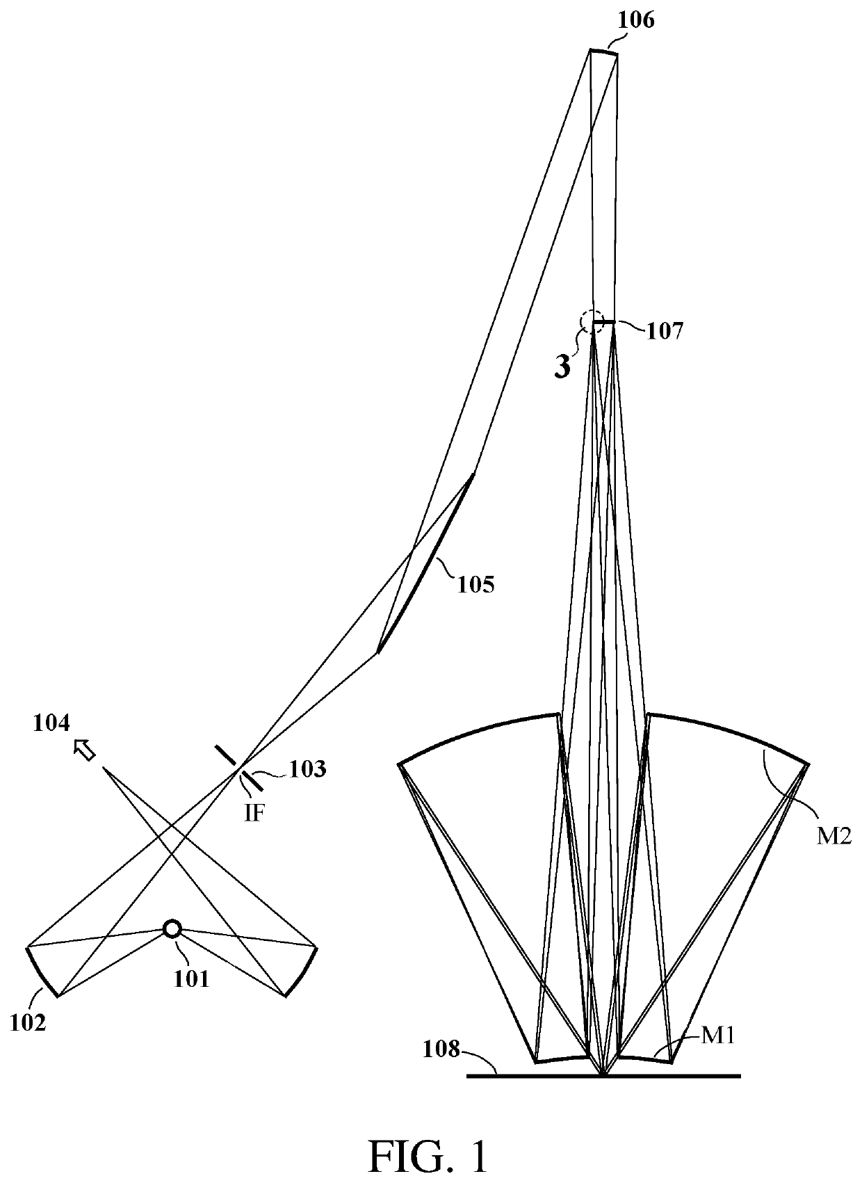
The patent describes a new design for an extreme ultraviolet (EUV) maskless lithography system that uses a microlens array to focus blended laser exposure onto a surface. The microlenses can be designed to concentrate light into specific spots, which are then imaged onto the surface using one or more projection optics (EUV mirrors). The resulting exposure image is created by modulating the spots on the surface. The use of diffractive elements in the projection optics can neutralize the chromatic effects of the microlenses, and the system can be designed to use a holographic mask or a reflection mask. This new design allows for improved optical efficiency and resolution, and the microlenses can be placed on a thin-film substrate to reduce complexity.

Problems solved by technology

Much of the complexity and expense of lithography scanners (“step-and-scan” systems) stems from the need to cover a full wafer die, measuring 26 by 33 mm, in a single scan pass.
Older “steppers” (“step-and-repeat” systems) from the early days of lithography, which image the full mask aperture in a single static exposure step (without scanning), are more limited in how large an image field can be covered with acceptable optical resolution.
The cost-effectiveness of EUV scanners is limited by power and low optical efficiency, which can, in some cases, necessitate a significant throughput reduction to achieve adequate exposure dose.
Also, print quality can be limited by optical shadowing (“3-D effects”) in EUV masks resulting from oblique illumination on the mask, which is required to separate the incident and reflected light paths.
(Wavelength reduction might not be feasible for conventional EUV mask-projection lithography due to the very low refractive index contrast of available optical materials for 6.7 nm, which would result in severe mask 3-D effects and a drastic reduction in the EUV mirrors' reflection bandwidth; Ref's.
This creates a problem for maskless lithography because the EUV microlenses are diffractive devices (similar to diffraction gratings), which exhibit significant chromatic aberration over the 3% transmission band.
Such lenses are relatively difficult to manufacture relative to binary-optic zone-plate lenses that are more commonly used for EUV applications (Ref. 5).

Method used


Image

  • EUV Lithography System with Diffraction Optics
  • EUV Lithography System with Diffraction Optics
  • EUV Lithography System with Diffraction Optics

Examples


Embodiment Construction

[0047]Maskless EUV lithography scanner

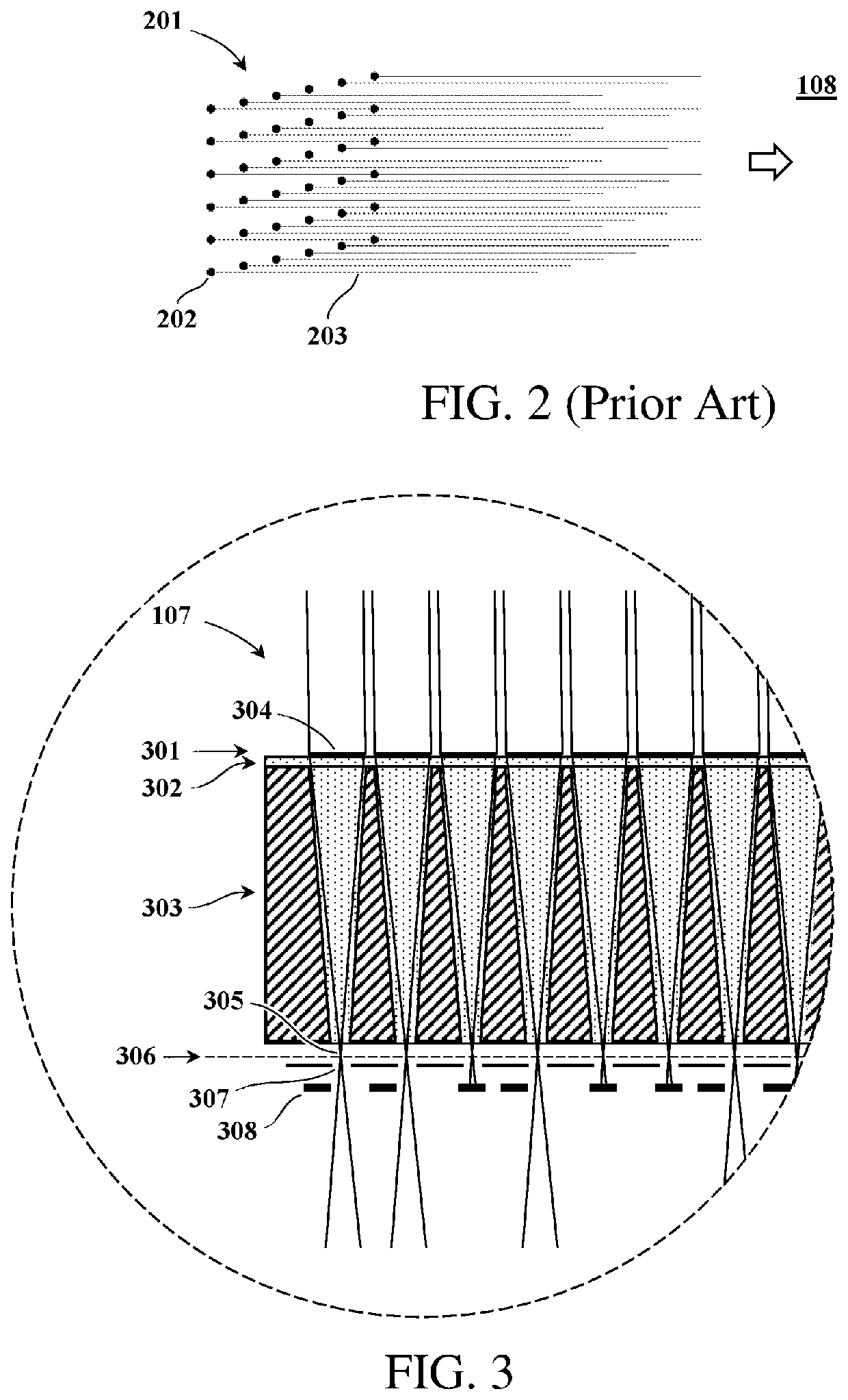
[0048]FIG. 1 shows a schematic cross-sectional view of a maskless EUV lithography scanner, in an illustrative embodiment. An LPP plasma 101 generates EUV radiation, which is focused by an ellipsoidal collection mirror 102 to an intermediate focus IF, where it is spatially filtered by a small aperture 103. (A portion 104 of the LPP power may be diverted to one or more other similar scanner modules.) The IF-transmitted radiation is directed by illumination optics comprising two illumination mirrors, grazing-incidence element 105 and near-normal-incidence element 106, onto microlens array 107. (Many alternative design forms for the illumination optics are possible.) The microlenses partition the radiation into a large number of individual convergent beams (e.g., approximately 2 million). A projection system comprising two axially-symmetric, annular mirrors M1 and M2 focuses the beams onto an array of diffraction-limited focal spots on a writing sur...


PUM

PropertyMeasurementUnit
wavelengthaaaaaaaaaa
relative speedaaaaaaaaaa
diameteraaaaaaaaaa

Abstract

A maskless, extreme ultraviolet (EUV) lithography scanner uses an array of microlenses, such as binary-optic, zone-plate lenses, to focus EUV radiation onto an array of focus spots (e.g. about 2 million spots), which are imaged through projection optics (e.g., two EUV mirrors) onto a writing surface (e.g., at 6X reduction, numerical aperture 0.55). The surface is scanned while the spots are modulated to form a high-resolution, digitally synthesized exposure image. The projection system includes a diffractive mirror, which operates in combination with the microlenses to achieve point imaging performance substantially free of geometric and chromatic aberration. Similarly, a holographic EUV lithography stepper can use a diffractive photomask in conjunction with a diffractive projection mirror to achieve substantially aberration-free, full-field imaging performance for high-throughput, mask-projection lithography. Maskless and holographic EUV lithography can both be implemented at the industry-standard 13.5-nm wavelength, and could potentially be adapted for operation at a 6.7-nm wavelength.

Description

CROSS-REFERENCE TO RELATED APPLICATION(S)[0001]This application claims the benefit under 35 U.S.C. § 119(e) of the following two applications, both of which name Kenneth C. Johnson as the inventor, and both of which are incorporated by reference in their entirety for all purposes:[0002]U.S. Patent Application No. 62,911,467, filed Oct. 7, 2019 for “EUV Lithography System with Diffraction Optics;” and[0003]U.S. Patent Application No. 62,931,323, filed Nov. 6, 2019 for “EUV Lithography System with Diffraction Optics”.[0004]The substance of these applications was presented in June 2020 at the 2020 EUVL Workshop, paper P22 (https: / / euvlitho.com / ) and is posted on the vixra.org e-print archive:[0005]“EUV Lithography Design Concepts using Diffraction Optics”, July 2020, https: / / vixra.org / abs / 2007.0167BACKGROUND OF THE INVENTION[0006]This application pertains primarily to extreme ultraviolet (EUV) lithography in the context of semiconductor and microsystems manufacture. The disclosed metho...

Claims


Application Information

Patent Timeline
Patent Type & Authority Applications(United States)
IPC IPC(8): G03F7/20G02B5/18G02B17/08G02B27/42G02B26/08
CPCG03F7/70158G02B5/1885G02B17/0892G03F7/70283G02B26/0808G02B26/0816G02B27/4222G03F7/70383G03F7/70275G03F7/70033G02B3/0056
Inventor JOHNSON, KENNETH CARLISLE
Owner JOHNSON KENNETH CARLISLE
Learn More