
Power conversion module and magnetic component thereof

a technology of power conversion module and magnetic component, which is applied in the direction of power conversion system, dc-dc conversion, basic electric elements, etc., can solve the problems of low saturation current of soft-magnetic ferrite magnetic component, large volume and loss, and low power density of power conversion module, so as to reduce parasitic parameters, increase the power density of the power conversion module, and improve the effect of power density

Pending Publication Date: 2022-03-31
DELTA ELECTRONICS INC
View PDF0 Cites 0 Cited by
  • Summary
  • Abstract
  • Description
  • Claims
  • Application Information

AI Technical Summary

Benefits of technology

The present patent provides a power conversion module and its magnetic component. By arranging the magnetic component in the main body layer, the output end of the power device is directly connected to the magnetic component, reducing the parasitic impedance on the output current transmission path and increasing the power density of the module. The magnetic core set is embedded in the main body layer using a vertical arrangement in the closed path of the magnetic field lines, further reducing the parasitic parameters and increasing power density. The overall power density is improved while reducing the volume of the module. The power conversion module and magnetic component are designed to optimize the circuit and reduce the influence of parasitic parameters, achieving reduced volume and increased power density.

Problems solved by technology

Therefore, how to design a reasonable structure and layout for a power conversion module to improve the conversion efficiency and reduce the volume of the power conversion module is one of the hot issues in this technical field.
However, in the power conversion module, a large part of the volume and the loss are caused by the inductor magnetic core.
However, since the saturation magnetization of the soft-magnetic ferrite is low, the saturation current of the magnetic component made of the soft-magnetic ferrite is low.
In that, the inner diameter and the outer diameter of the magnetic core are different sufficiently, and it results in uneven distribution of losses in the iron powder magnetic core, which fails to meet the practical requirements.

Method used


Image

  • Power conversion module and magnetic component thereof
  • Power conversion module and magnetic component thereof
  • Power conversion module and magnetic component thereof

Examples


Embodiment Construction

[0046]The present disclosure will now be described more specifically with reference to the following embodiments. It is to be noted that the following descriptions of preferred embodiments of this disclosure are presented herein for purpose of illustration and description only. It is not intended to be exhaustive or to be limited to the precise form disclosed.

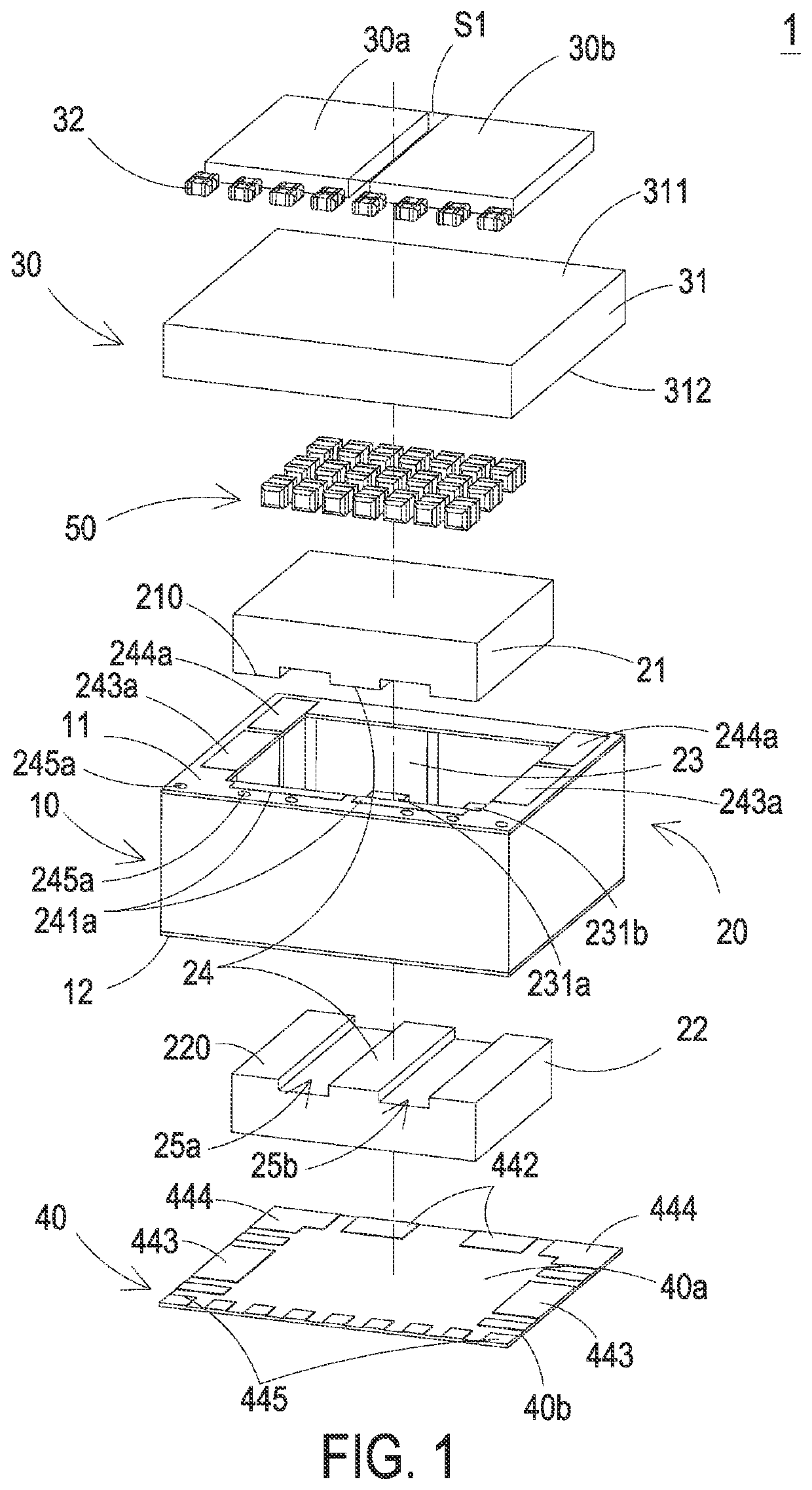
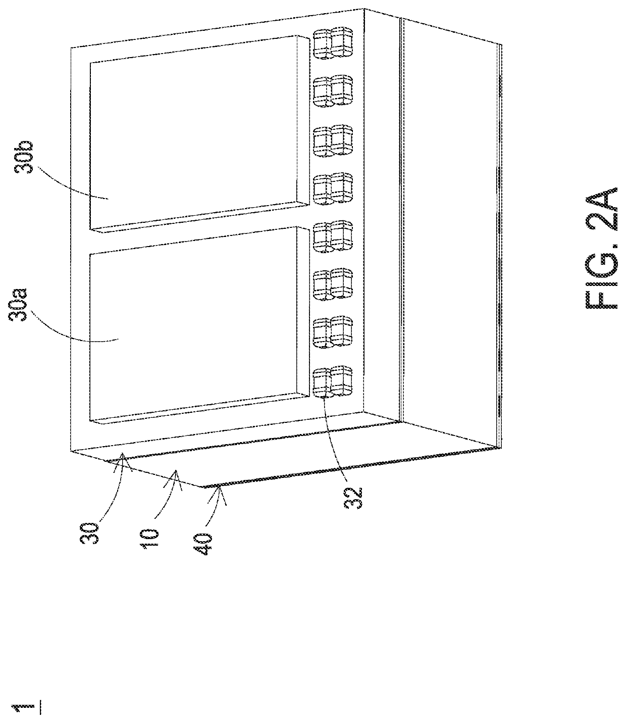
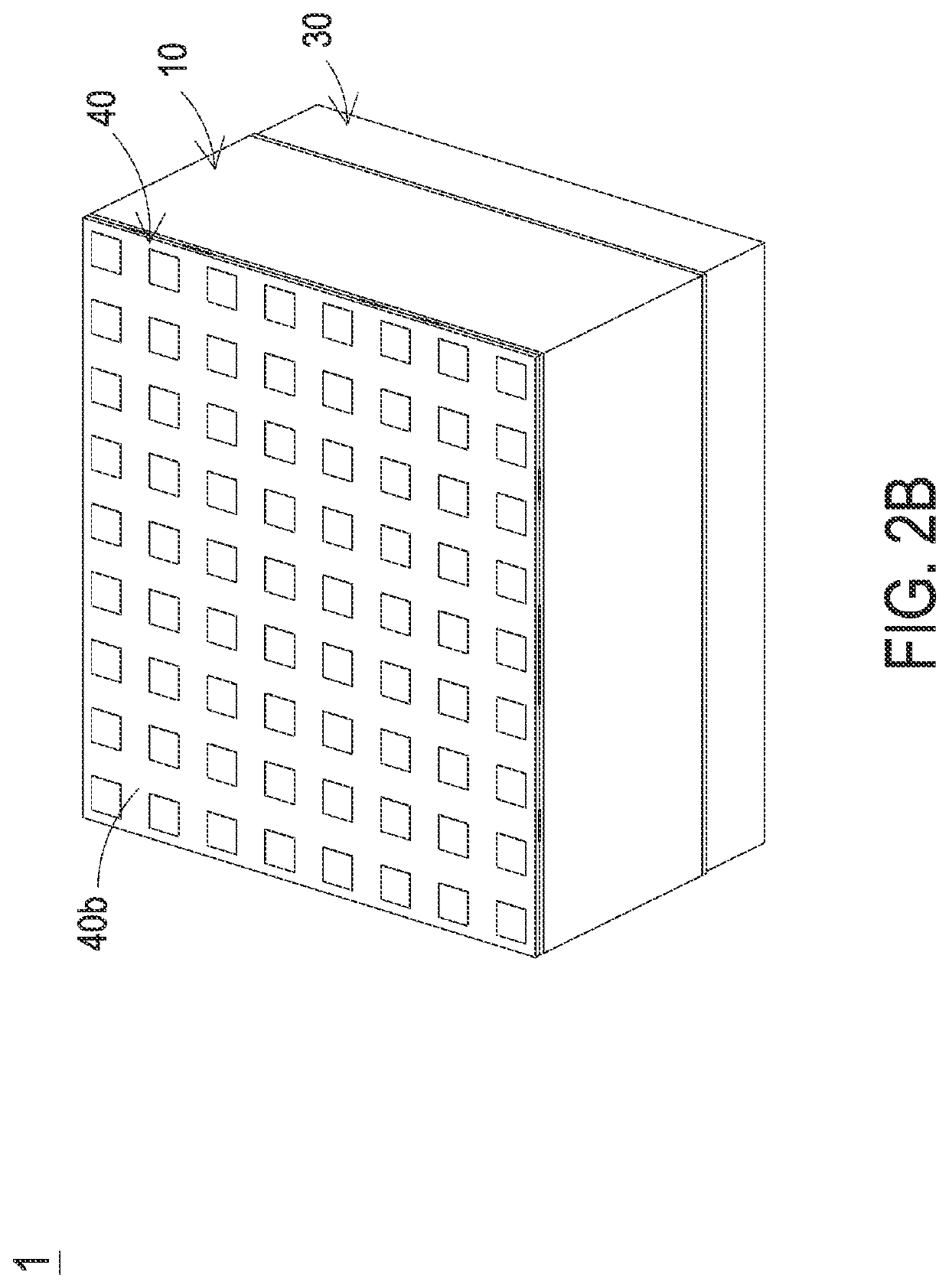
[0047]FIG. 1 is an exploded view illustrating a power conversion module according to a first embodiment of the present disclosure. FIGS. 2A and 2B are perspective structural views illustrating the power conversion module according to the first embodiment of the present disclosure. FIG. 3 shows the circuit topology corresponding to the power conversion module of the present disclosure. In the embodiment, the power conversion module 1 includes a magnetic component 20, a power device layer 30 and a pin layer 40. The magnetic component 20 includes a main body layer 10, a first magnetic core 21, a second magnetic core 22 and a condu...


PUM

PropertyMeasurementUnit
magneticaaaaaaaaaa
currentaaaaaaaaaa
power conversion efficiencyaaaaaaaaaa

Abstract

The present disclosure provides a power conversion module including a magnetic component and a power device layer. The magnetic component includes a main body layer, a first magnetic core, a second magnetic core and a conductor. The main body layer includes a first surface and a second surface opposite to each other. The first magnetic core is embedded in the main body layer and adjacent to the first surface. The second magnetic core is embedded in the main body layer and adjacent to the second surface. The first magnetic core and the second magnetic core are connected to form plural magnetic columns. The conductor is embedded between the first surface and the second surface. The conductor is partially disposed between the plural magnetic columns. The power device layer is disposed on the first surface. The power device layer includes a power device electrically connected to conductor.

Description

CROSS-REFERENCE TO RELATED APPLICATION[0001]This application claims priority to China Patent Application No. 202011022986.4, filed on Sep. 25, 2020. The entire contents of the above-mentioned patent application are incorporated herein by reference for all purposes.FIELD OF THE INVENTION[0002]The present disclosure relates to a technology field of power electronic devices, and more particularly to a power conversion module and a magnetic component thereof.BACKGROUND OF THE INVENTION[0003]Power electronic device is an essential part of a device applied in the industries of electric power, electronics, electric motors and energy sources in recently years. Ensuring the long-term stable operation of the power electronic device and improving the power conversion efficiency of the power electronic device have always been an important purpose pursued by those skilled in the art.[0004]With the rapid development of cloud computing and mobile communication, high-power DC / DC power conversion mo...

Claims


Application Information

Patent Timeline
Patent Type & Authority Applications(United States)
IPC IPC(8): H01F27/26H01F27/30
CPCH01F27/263H01F27/306H01F27/266H01F27/2852H01F27/06H01F2027/065H02M3/1584H02M3/003
Inventor XIONG, YAHONGCUI, JUNGUOYANG, KAIJIANGU, DONGJIE
Owner DELTA ELECTRONICS INC
Learn More