
Process for manufacturing an aluminum alloy part

a manufacturing method and technology for aluminum alloys, applied in the direction of additive manufacturing, process efficiency improvement, additive manufacturing apparatus, etc., can solve the problems of limited mechanical properties, poor mechanical properties of solutions at high temperature, and high cost of solutions in powder form, so as to reduce roughness, reduce the harmful effect of mechanical strength, and increase the hardness of products obtained

Pending Publication Date: 2021-09-02
C TEC CONSTELLIUM TECH CENT
View PDF1 Cites 3 Cited by
  • Summary
  • Abstract
  • Description
  • Claims
  • Application Information

AI Technical Summary

Benefits of technology

The patent text discusses a method for improving the hardness and properties of a material. The method involves heat treatment and / or hot isostatic compression, which can increase the hardness of the material. Additionally, the text mentions the option of further treatments such as machining, chemical, electrochemical, or mechanical surface treatments to improve roughness, corrosion resistance, and resistance to fatigue cracks. Overall, the method can enhance the properties of the material and make it more durable.

Problems solved by technology

These alloys offer very good suitability for the SLM method but suffer from limited mechanical properties.
However, this solution suffers from a high cost in powder form related to the high scandium content thereof (˜0.7% Sc) and the need for a specific atomization process.
This solution also suffers from poor mechanical properties at high temperature, for example above 150° C. Addalloy™ developed by NanoAl (WO 2018 / 00935 A1) is an Al Mg Zr alloy.
This alloy suffers from limited mechanical properties with a hardness peak of approximately 130 HV.

Method used


Image

  • Process for manufacturing an aluminum alloy part
  • Process for manufacturing an aluminum alloy part

Examples


example 1

[0110]Two alloys according to the present invention, called Innov1 and Innov2, and an 8009 alloy of the prior art, were cast in a copper mold using an Induthem VC 650V machine for obtaining ingots 130 mm high, 95 mm wide and 5 mm thick. The composition of the alloys is given as a percentage proportion by mass in the following table 1.

TABLE 1AlloysSiFeVNiZrCrReference1.88.651.3———(8009)Innov1—0.17—324Innov2—0.21—526

[0111]The alloys as described in table 1 above were tested by a fast prototyping method. Samples were machined for sweeping the surface with a laser, in the form of slices with dimensions 60×22×3 mm, from the ingots obtained above. The slices were placed in an SLM machine and the surface was swept with a laser following the same sweep strategy and method conditions representative of those used for the SLM method. It was in fact found that it was possible in this way to evaluate the suitability of the alloys for the SLM method and in particular the surface quality, sensitiv...

example 2

[0121]An alloy according to the present invention having the composition as presented in Table 3 below, in percentages by mass, was cast in the form of an ingot.

TABLE 3AlloyCrNiZrInnov3432

[0122]The ingot was next transformed into powder by atomization using a VIGA (vacuum inert gas atomization) atomizer. The particle size of the powder was measured by laser diffraction with a Malvern 2000 instrument and is given in Table 4 below, in μm.

TABLE 4AlloyD10D90Innov31150

[0123]The powder of the Innov3 alloy was used successfully for tests in accordance with the SLM technique using a FormUp 350 selective laser melting machine, sold by the company AddUp. These tests were performed with the following parameters: thickness of layer: 60 μm, power of the laser 370 W, heating of the plate to around 200° C., vector separation 0.13 mm, speed of the laser 1000 mm / s.

[0124]Cylindrical test pieces (45 mm high and 11 mm in diameter) were impressed for tensile tests in the construction direction Z (the mo...


PUM

PropertyMeasurementUnit
temperatureaaaaaaaaaa

Abstract

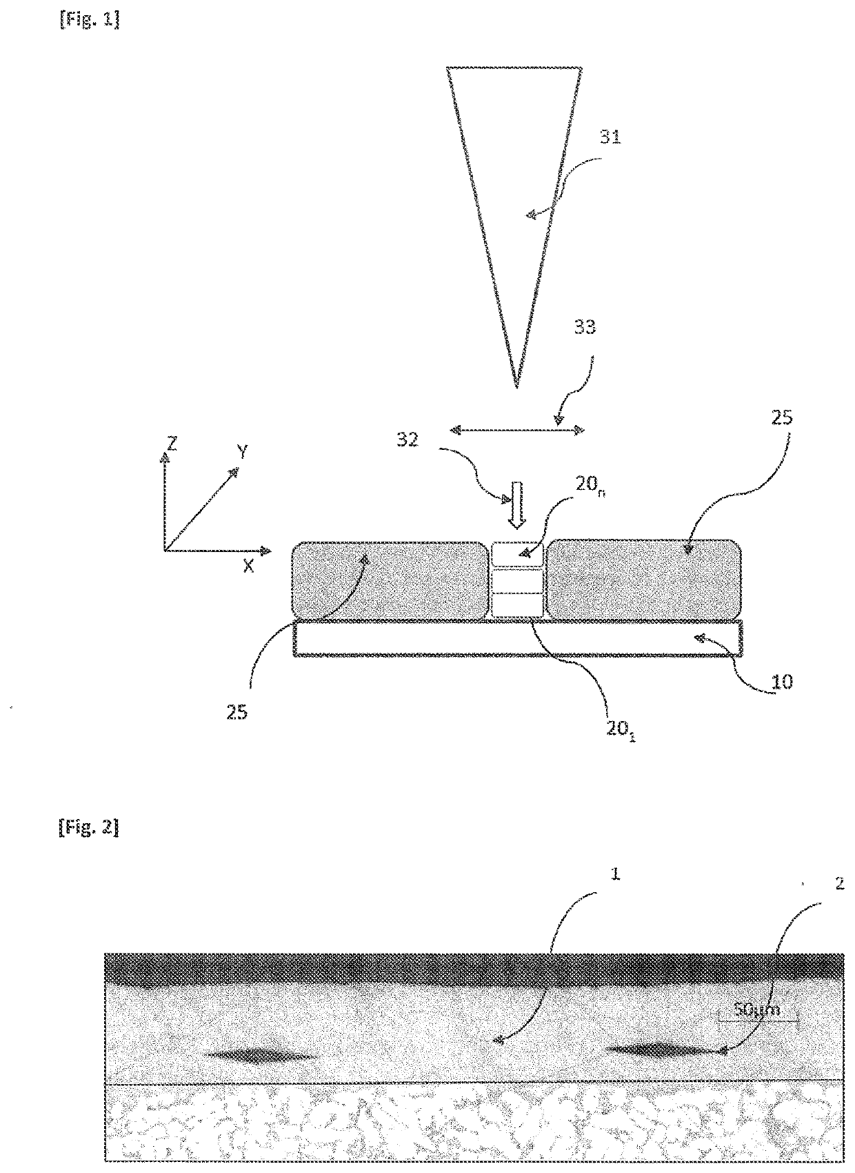
The invention relates to a process for manufacturing a part, involving forming consecutive solid metal layers (201 . . . 20n) that are stacked on top of one another, each layer describing a pattern defined on the basis of a numerical model {M), each layer being formed by depositing a metal (25), referred to as filling metal, the filling metal being subjected to an input of energy so as to melt and constitute said layer upon solidifying, the filling metal being in the form of a powder (25) that is exposed to an energy beam (32), resulting in melting followed by solidification such that a solid layer (201 . . . 20n) is formed, the process being characterized in that the filling metal (25) is an aluminum alloy comprising at least the following alloying elements: —Ni, in a moiety of 1 to 6%, preferably 1 to 5.5%, more preferably 2 to 5.5%; —Cr, in a moiety of 1 to 7%, preferably 3 to 6.5%; —Zr, in a moiety of 0.5 to 4%, preferably 1 to 3%; —Fe, in a moiety of no more than 1%, preferably between 0.05 and 0.5%, more preferably between 0.1 and 0.3%; —Si, in a moiety of no more than 1%, preferably no more than 0.5%. The invention also relates to a part obtained by said process. The alloy used in the additive manufacturing process according to the invention makes it possible to obtain parts with remarkable features.

Description

TECHNICAL FIELD[0001]The technical field of the invention is a method for manufacturing an aluminum alloy part, using an additive manufacturing technique.PRIOR ART[0002]Since the 1980s, additive manufacturing techniques have developed. They consist of forming a part by adding material, which is the opposite of machining techniques, which aim to remove material. Previously confined to prototyping, additive manufacture is now operational for the mass production of industrial products, including metal parts.[0003]The term “additive manufacturing” is defined, in accordance with the French standard XP E67-001, as a “set of methods for manufacturing, layer by layer, by adding material, a physical object from a digital object”. The standard ASTM F2792 (January 2012) also defines additive manufacturing. Various additive manufacturing methods are also defined and described in the standard ISO / ASTM 17296-1. Recourse to additive manufacturing for producing an aluminum part with low porosity wa...

Claims


Application Information

Patent Timeline
Patent Type & Authority Applications(United States)
IPC IPC(8): C22C21/00B22F10/28B33Y70/00C22C1/04C22C32/00C22F1/04B33Y40/20
CPCC22C21/00B22F10/28B33Y70/00B22F2301/052C22C32/0047C22F1/04B33Y40/20C22C1/0416C22C32/0052C22C32/0073Y02P10/25B22F10/62B22F10/66B22F10/36B22F10/64B22F10/25
Inventor CHEHAB, BECHIR
Owner C TEC CONSTELLIUM TECH CENT
Learn More