
Process for manufacturing an aluminium alloy part

a manufacturing method and alloy technology, applied in the direction of process efficiency improvement, additive manufacturing, manufacturing tools, etc., can solve the problems of limited mechanical properties, poor mechanical properties, and high powder cost, so as to improve corrosion resistance, reduce roughness, and increase the hardness of the product obtained

Pending Publication Date: 2021-08-26
C TEC CONSTELLIUM TECH CENT
View PDF1 Cites 1 Cited by
  • Summary
  • Abstract
  • Description
  • Claims
  • Application Information

AI Technical Summary

Benefits of technology

The patent is about a method for improving the hardness and fatigue properties of a material. The method involves adding specific elements to an alloy, such as Mn, Ti, W, Nb, Ta, Y, Yb, Nd, Er, Cr, Zr, Hf, Sc, Ce, mischmetal, and avoiding the addition of certain other elements, such as Sc and Bi. The resulting material can then be treated with heat treatment and / or hot isostatic compression to increase its hardness. Additionally, the material can also undergo surface treatments, such as machining, chemical, electrochemical, or mechanical treatments, to reduce roughness, improve corrosion resistance, and prevent fatigue cracking initiation. Overall, this patent provides a way to create materials with improved hardness and fatigue properties.

Problems solved by technology

These alloys offer very good suitability for the SLM method but suffer from limited mechanical properties.
However, this solution suffers from a high cost in powder form related to the high scandium content thereof (˜0.7% Sc) and to the need for a specific atomisation process.
This solution also suffers from poor mechanical properties at high temperature, for example above 150° C. The mechanical properties of the aluminium parts obtained by additive manufacturing are dependent on the alloy forming the solder metal, and more precisely the composition thereof, and the parameters of the additive manufacturing method and of the heat treatment applied.

Method used


Image

  • Process for manufacturing an aluminium alloy part

Examples


example 1

SLM on Discs

[0103]The alloys as described in table 1 above were tested by a fast prototyping method.

[0104]Samples were machined for sweeping the surface with a laser, in the form of discs with a thickness of 5 mm and a diameter of 27 mm, from the ingots obtained above. The discs were placed in an SLM machine and sweeps of the surface were carried out with a laser, following the same sweep strategy and method conditions representative of those used for the SLM method. It was in fact found that it was possible in this way to evaluate the suitability of the alloys for the SLM method and in particular the surface quality, sensitivity to hot cracking, hardness in the untreated state and hardness after heat treatment.

[0105]Under the laser beam, the metal melts in a bath 10 to 350 μm thick. After the passage of the laser, the metal cools quickly as in the SLM method. After the laser sweep, a fine surface layer 10 to 350 μm thick was melted and then solidified. The properties of the metal i...

example 2

SLM on Powder

[0116]Ingots cast from the compositions described in table 1 above were atomised by the UTBM (Université de Technologie de Belfort Montbéliard) in order to obtain a powder by gas jet atomisation (the method described above). Granulometric analysis of the powders obtained was carried out by laser diffraction using a Malvern Mastersizer 2000 granulometer in accordance with ISO 13320. The curve describing the change in the volume fraction as a function of the diameter of the particles forming the powder generally describes a distribution that can be assimilated to a Gaussian distribution. The 10%, 50% (median) and 90% fractiles of the distribution obtained are generally referred to as D10, D50 and D90 respectively.

[0117]The D10, D50 and D90 characteristics of the powders obtained are given in table 4 below.

TABLE 4AlloyD10 (μm)D50 (μm)D90 (μm)Reference (8009)33.552.381.2Innov142.358.181.2Innov239.560.793.6Innov358.688.3132

[0118]Thus it is possible to manufacture powders fro...


PUM

PropertyMeasurementUnit
temperatureaaaaaaaaaa

Abstract

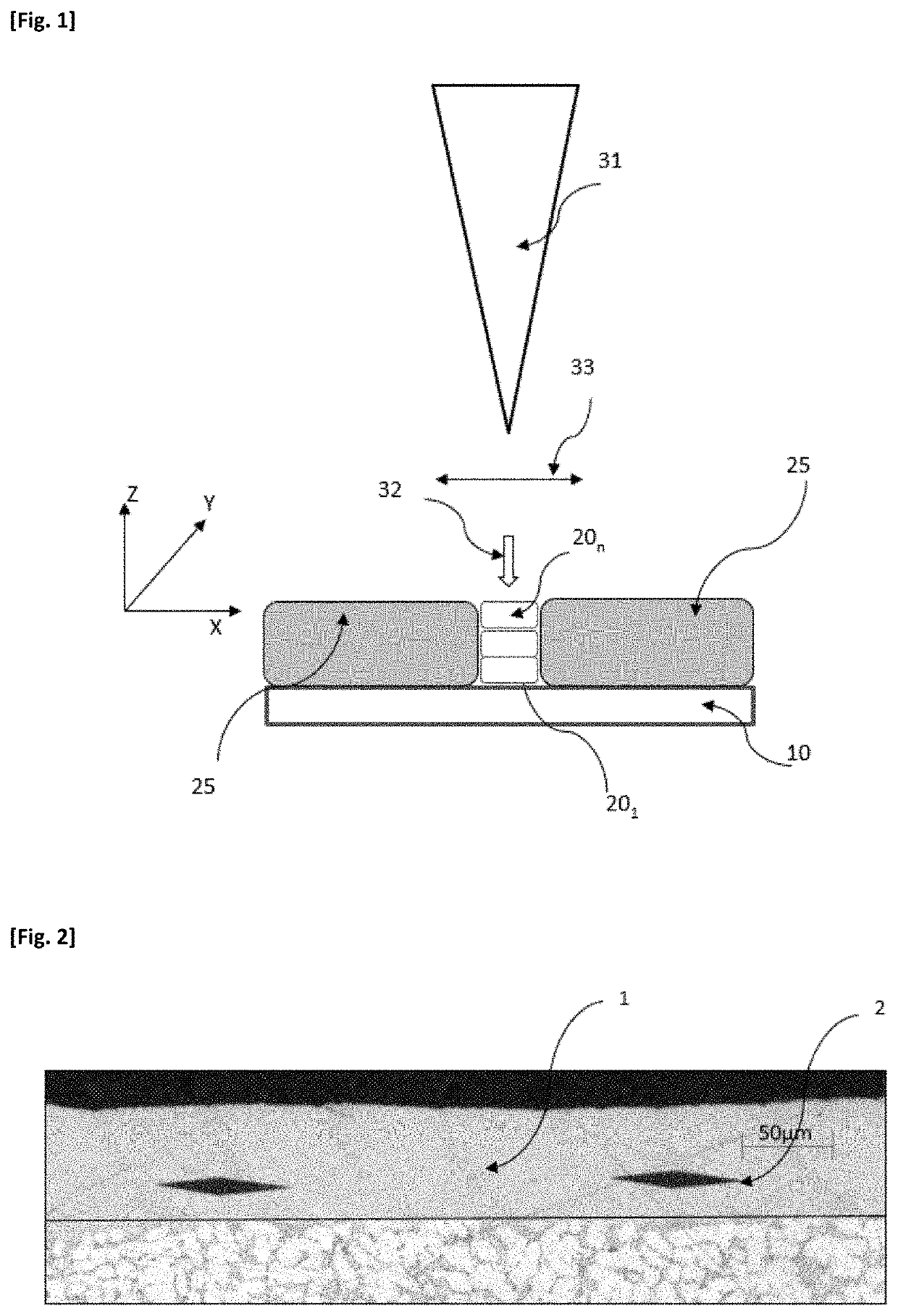
The invention relates to a process for manufacturing a part comprising a formation of successive solid metal layers (201 . . . 20n), superposed on one another, each layer describing a pattern defined using a numerical model (M), each layer being formed by the deposition of a metal (25), referred to as solder, the solder being subjected to an input of energy so as to start to melt and to constitute, by solidifying, said layer, wherein the solder takes the form of a powder (25), the exposure of which to an energy beam (32) results in melting followed by solidification so as to form a solid layer (201 . . . 20n), the process being characterized in that the solder (25) is an aluminium alloy comprising at least the following alloy elements: —Si; in a weight fraction of from 0 to 4%, preferably from 0.5% to 4%, more preferably from 1% to 4% and more preferably still from 1% to 3%; —Fe in a weight fraction of from 1% to 15%, preferably from 2% to 10%; —V in a fraction of from 0 to 5%, preferably from 0.5% to 5%, more preferentially from 1% to 5%, and more preferentially still from 1% to 3%; at least one element chosen from Ni, La and / or Co, in a weight fraction of from 0.5% to 15%, preferably from 1% to 10%, more preferably from 3% to 8% each for Ni and Co, in a weight fraction of from 1% to 10%, preferably from 3% to 8% for La, and in a weight fraction of less than or equal to 15%, preferably less than or equal to 12% in total. The invention also relates to a part obtained by this process. The alloy used in the additive manufacturing process according to the invention makes it possible to obtain parts with remarkable characteristics.

Description

TECHNICAL FIELD[0001]The technical field of the invention is a method for manufacturing an aluminium alloy part, using an additive manufacturing technique.PRIOR ART[0002]Since the 1980s, additive manufacturing techniques have been developed. They consist of forming a part by adding material, which is the opposite to machining techniques, which aim to remove material. Previously confined to prototyping, additive manufacturing is now operational for the mass production of industrial products, including metal parts.[0003]The term “additive manufacturing” is defined, in accordance with the French standard XP E67-001, as a “set of methods for manufacturing, layer by layer, by adding material, a physical object from 5a digital object”. ASTM F2792 (January 2012) also defines additive manufacturing. Various methods for additive manufacturing are also defined and described in ISO / ASTM 17296-1. The use of additive manufacturing for producing an aluminium part, with low porosity, was described...

Claims


Application Information

Patent Timeline
Patent Type & Authority Applications(United States)
IPC IPC(8): B22F10/28B33Y10/00B33Y40/20B33Y70/00B22F10/64C22C21/00C22F1/04B23K26/34B23K26/354
CPCB22F10/28B33Y10/00B33Y40/20B33Y70/00B22F10/64B33Y80/00C22F1/04B23K26/34B23K26/354B22F2301/052C22C21/00C22C1/0408Y02P10/25B22F3/15B22F3/24B22F7/008B22F7/08B22F2003/248C22C1/0416C22C1/10C22C32/0047B22F10/36B22F10/25
Inventor CHEHAB, BECHIRJARRY, PHILIPPE
Owner C TEC CONSTELLIUM TECH CENT
Learn More