
Method for machining the edges of glass elements and glass element machined according to the method

Active Publication Date: 2018-12-27
SCHOTT AG
View PDF0 Cites 4 Cited by
  • Summary
  • Abstract
  • Description
  • Claims
  • Application Information

AI Technical Summary

Benefits of technology

The patent text describes a new method for producing high-quality glass edges using a laser. By using this method, subsequent process steps such as edge grinding can be performed more precisely, which speeds up the overall process. Additionally, less material has to be removed in the grinding step, resulting in faster processing speeds. The quality of the glass edge produced is comparable to conventionally ground edges and can be combined with other processes for final creation of the edge. This method reduces the cost of the process chain, increases processing speed, and reduces tool wear while also allowing for the production of glass articles with higher accuracies.

Problems solved by technology

Each of these methods has certain drawbacks, such as, for instance, a low mechanical strength or a low dimensional accuracy.
Thus, during scoring and breaking, for example, the shape errors increase with increasing thickness owing to breaks induced at an angle.
In the different separating processes, however, conchoidal fractures and microcracks can occur at the edges, as a result of which the resulting strength is greatly reduced or the intended contour of the workpiece is altered.
This is tedious, because finer grinding processes also remove the material more slowly, even though, this notwithstanding, a thicker layer needs to be ground away for elimination of the subsurface damages.
Oftentimes, in this state, the surface finishes do not meet the optical requirements in regard to transparency or roughness, for example.
In this case, there exists the problem that, in particular in the case of glass that has not been prestressed, the small perforated edge regions (with triangular cross section) have to be split off in a process-safe manner from bulk material and removed free of splinters.
These two strip-shaped regions thereby created differ, among other things, in terms of their surface quality, although, as a rule, this difference is not perceivable to the naked eye.

Method used


Image

  • Method for machining the edges of glass elements and glass element machined according to the method
  • Method for machining the edges of glass elements and glass element machined according to the method
  • Method for machining the edges of glass elements and glass element machined according to the method

Examples


Embodiment Construction

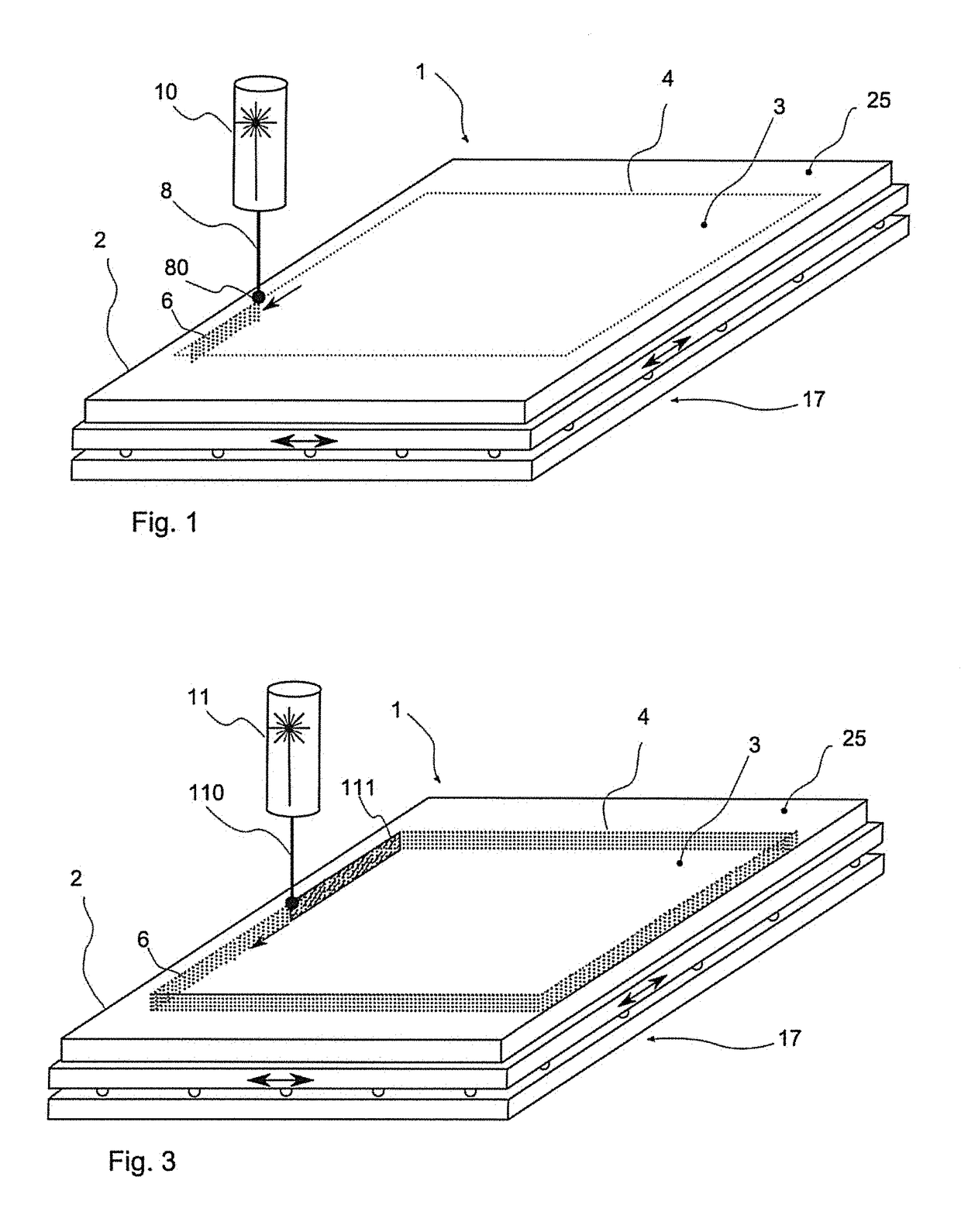
[0032]For the method according to the invention, a glass or glass ceramic element 3 with fixed dimensions is worked out of a flat glass or glass ceramic part 2. FIG. 1 shows an exemplary embodiment of a laser processing device 1 for carrying out this step of the method. A pre-separation is carried out through insertion of elongated or filamentary damages along a provided separating line 4. The imaginary separating line 4 and accordingly also the course of the inserted damages 6 trace the outer contour of the glass or glass ceramic element 3 that is to be released.

[0033]Accordingly, for the example shown in FIG. 1, a rectangular element is to be cut out of the glass part or glass ceramic part 2 corresponding to the course of the imaginary separating line. The separating line 4 need not necessarily run along the entire outer contour. For example, it would also be conceivable that the outer contour of the glass or glass ceramic part 2 and of the glass or glass ceramic element 3 that is...


PUM

PropertyMeasurementUnit
Thicknessaaaaaaaaaa
Distanceaaaaaaaaaa
Feed rateaaaaaaaaaa

Abstract

A method for the production of glass or glass ceramic elements from flat glass or glass ceramic parts is provided where the edges of the glass or glass ceramic elements are treated by a combination of two processes. The flat glass or glass ceramic element with an edge surface connecting the two side surfaces is produced. The edge surface has at least one first elongated, strip-shaped edge region and at least one second elongated strip-shaped edge region, which are formed by a ground edge. The edge regions extend in the longitudinal direction along the edge surface and along the side surfaces. The first edge region has elongated parallel filamentary damages that are parallel and adjacent to one another and, in particular, spaced apart equidistantly, in the longitudinal direction thereof extending transversely to the side surfaces and along the surface of the first edge region.

Description

CROSS REFERENCE TO RELATED APPLICATIONS[0001]This application is a continuation of International Application No. PCT / EP2016 / 079411 filed Dec. 1, 2016, which claims the benefit under 35 USC 119(a) of German Application No. 10 2016 102 768.5 filed Feb. 17, 2016, the entire contents of all of which are incorporated herein by reference.BACKGROUND1. Field of the Invention[0002]The invention relates, in general, to the processing of the edges of sheets of glass. In particular, the invention relates to a processing of the edges with different methods.2. Description of Related Art[0003]Typically, for the production of a flat glass or glass ceramic element, a larger flat element is divided by one or a plurality of separating steps and thereby brought to the desired dimension. Subsequently, in general, a processing of the edge is necessary. For separation, mechanical scoring and breaking has become established practice, but also fusing or abrasive processes such as water-jet separation are kn...

Claims


Application Information

Patent Timeline
IPC IPC(8): C03B33/02B23K26/00B23K26/53B23K26/0622B24D3/00
CPCC03B33/0222B23K26/0006B23K26/53B23K26/0624B24D3/00B23K2103/54
Inventor PLAPPER, VOLKERWAGNER, FABIANORTNER, ANDREASSEIDL, ALBRECHTLENTES, FRANK-THOMAS
Owner SCHOTT AG
Learn More