Method and apparatus for drone detection and disablement

Active Publication Date: 2018-01-09
WEINSTEIN LEE +1
View PDF6 Cites 40 Cited by
  • Summary
  • Abstract
  • Description
  • Claims
  • Application Information

AI Technical Summary

Benefits of technology

The present invention provides innovative technologies to detect, locate, and disable UAVs near a secure perimeter, as well as remote control devices used to control them. This is done using inexpensive acoustic and RF detection and localization technology, which takes advantage of the fact that UAVs and remote control devices generate sound and RF signals when in flight. The invention also increases certainty of detection by combining two detection modalities, such as acoustic and RF, or acoustic or RF combined with optical reflection. The invention can disable UAVs without causing collateral damage, and is unobtrusive and can be installed at a small facility. Additionally, the invention can detect and locate banned or contraband objects dropped from altitude or lobbed over a restricted area.

Problems solved by technology

Remote-controlled unmanned aerial vehicles have become inexpensive and now represent a potential security threat to both government, corporate, and private facilities.
Such techniques are not suitable for use in an urban area unless they can be highly targeted, and are only targeted at real threats.
While each of these techniques have applications in urban warfare, these techniques have the potential to cause collateral damage in a peace-time suburban or urban setting.
A shaped antenna is often far less expensive than an antenna array of equivalent antenna gain, but if a shaped antenna is to be used to locate objects throughout a volume of space, it must be continually moved in a repetitive pattern (for instance rotated in a circle), and the mechanism to do the repetitive movement may itself be expensive and unreliable compared to the electronics needed to drive an array of fixed-position antennas.
Methods known in the art for disabling or destroying aerial targets in warfare (both battlefield warfare and urban warfare) usually use explosively propelled projectiles (such as disclosed by Rotkopf), or bursts of high-powered electromagnetic energy (such as disclosed by Keller), or extremely loud sounds produced by timed detonations (such as disclosed by Fullerton), however, these methods all have the potential to cause undesirable damage should they be used in peacetime in an urban or suburban environment.

Method used


Image

  • Method and apparatus for drone detection and disablement
  • Method and apparatus for drone detection and disablement
  • Method and apparatus for drone detection and disablement

Examples


Embodiment Construction

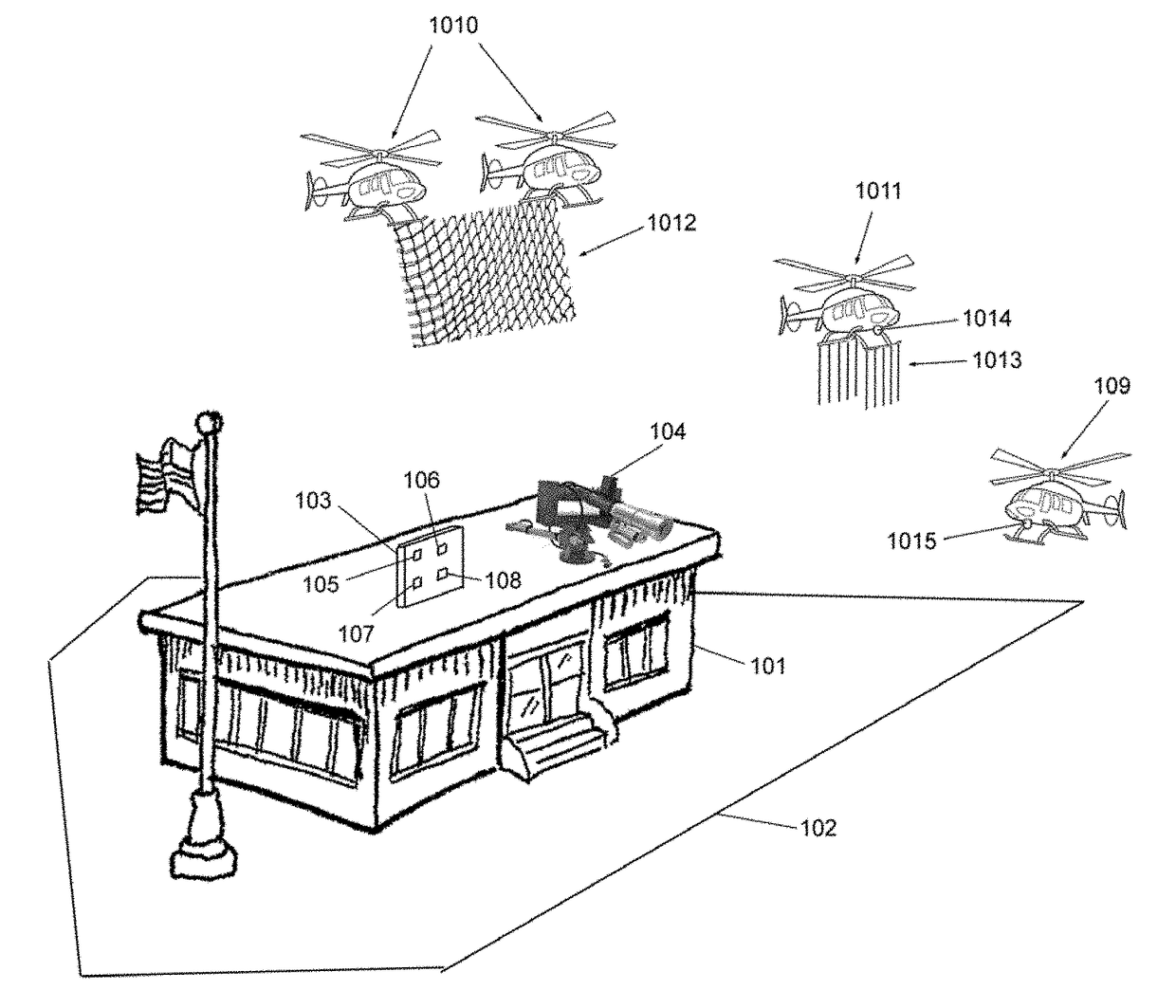
[0044]FIG. 1 depicts a building 101 within a perimeter 102. Building 101 is equipped with a UAV detection antenna array 103, and servo-aimed assembly 104. In a preferred embodiment, servo-aimed assembly 104 includes a camera, a directional light source, and a water canon according to aspects of the present invention. In a preferred embodiment, antenna array 103 includes at least three spatially disparate antenna elements.

[0045]Within this document, the word antenna may be used to refer in some instances to an element which receives Radio frequency (RF) electromagnetic energy and converts such energy to an electrical signal. The word antenna may alternately be used to refer to an element such as a microphone, which receives acoustic energy and converts it to an electrical signal. The word antenna may alternately be used to refer to an element such as a pixel in a video camera image sensor, which receives optical energy and converts it into an electrical signal. Within this document a...


PUM


Abstract

A preferred embodiment of a method and apparatus for detection and disablement of an unidentified aerial vehicle (UAV) includes arrays of antenna elements receiving in two modalities (for instance radio frequency (RF) and acoustic modalities, or RF and optical modalities). Signal processing of outputs from multiple antenna arrays locates a potential UAV at specific coordinates within a volume of space under surveillance, and automatically aims video surveillance and a short-range projectile launcher at the UAV, and may automatically fire the projectile launcher to down the UAV.

Description

FIELD OF THE INVENTION[0001]The field of the invention relates to unmanned aerial vehicles (also known as drones or UAVs) and more specifically to the detection of and disablement of drones in the vicinity of a facility or property, to protect against security breach, terrorism, spying on property, or importation of contraband or other dangerous or illegal substances, etc.BACKGROUND OF THE INVENTION[0002]Remote-controlled unmanned aerial vehicles have become inexpensive and now represent a potential security threat to both government, corporate, and private facilities. For example, a large variety of remote-controlled quadracopters (aerial vehicles with four sets of rotor wings, which are inherently stable and easy to fly) have become available on the hobby market in recent years. Quadracopters available for the hobby market range from inexpensive unit such as the UDI U818A quadracopter with on-board remote-viewable low-definition video, to units in the $3000 price range such as the...

Claims


Application Information

Patent Timeline
IPC IPC(8): B64C39/02G01S13/06B64F1/02G01S15/06B64D1/18G01S17/06
CPCB64C39/024G01S13/06G01S15/06G01S17/06B64D1/18B64F1/02B64C2201/14B64C2201/126B64C2201/182B64F1/0297B64F1/027B64F1/0295B64U2101/30B64U2101/16B64U70/30B64U2101/00B64U2201/00
Inventor WEINSTEIN, LEEGAINSBORO, JAY
Owner WEINSTEIN LEE
Why Eureka
Try Eureka