
Modular electric system

a module and electric system technology, applied in the direction of lighting support devices, coupling device connections, light source combinations, etc., can solve the problems of affecting the operation of the module, so as to achieve the effect of easy removal and removal of the base modul

Active Publication Date: 2010-08-26
SIGNIFY HLDG BV
View PDF3 Cites 60 Cited by
  • Summary
  • Abstract
  • Description
  • Claims
  • Application Information

AI Technical Summary

Benefits of technology

[0005]In view of the above, it is therefore an object of the present invention to design the above mentioned modular electric system such that the disadvantages are overcome. Particularly, the modular electric system must allow that the load modules may be removably placeable on the base module easily and without the risk of wrong connections between the base module and the load module.
[0018]This measure has the advantage that the provision of such arrangements allows to define specific positions for load modules precisely.
[0020]This measure has the advantage, that the position of the load module on the base module may further be limited. Particularly, the load module may be placed only in one angular position.
[0023]Hence, this measure has the advantage that the form / design of the magnet elements is very flexible and may be adapted to many applications. Also, magnetic strips as magnet elements are very cost effective.

Problems solved by technology

These connectors, however, encounter several problems.
For example, snap-on connections wear out with time, so that they have a limited lifetime, particularly if used frequently.
Further, they are visible if the parts are removed, leaving an ugly view.
In most cases standard connectors are used, which, however, are bulky and also visible, which decreases the beauty of the system and limits the scope of the design possibilities.
Further with the increase in electrical contacts between the parts of the system, the risk of wrong connections between the parts increases and hence the risk of damage due to e.g. short circuits.
These measures, however, increase costs.

Method used


Image

  • Modular electric system
  • Modular electric system
  • Modular electric system

Examples


Embodiment Construction

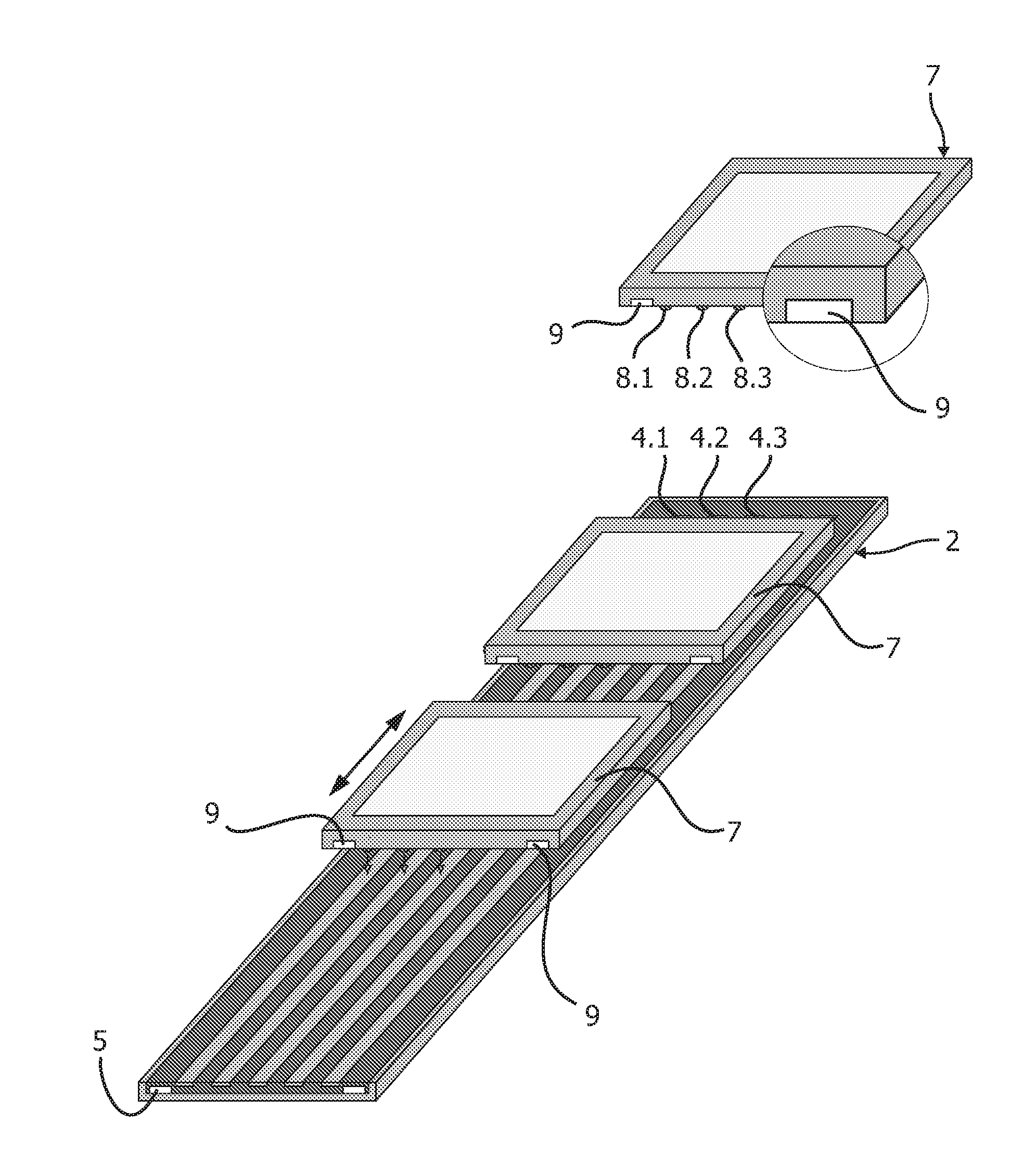
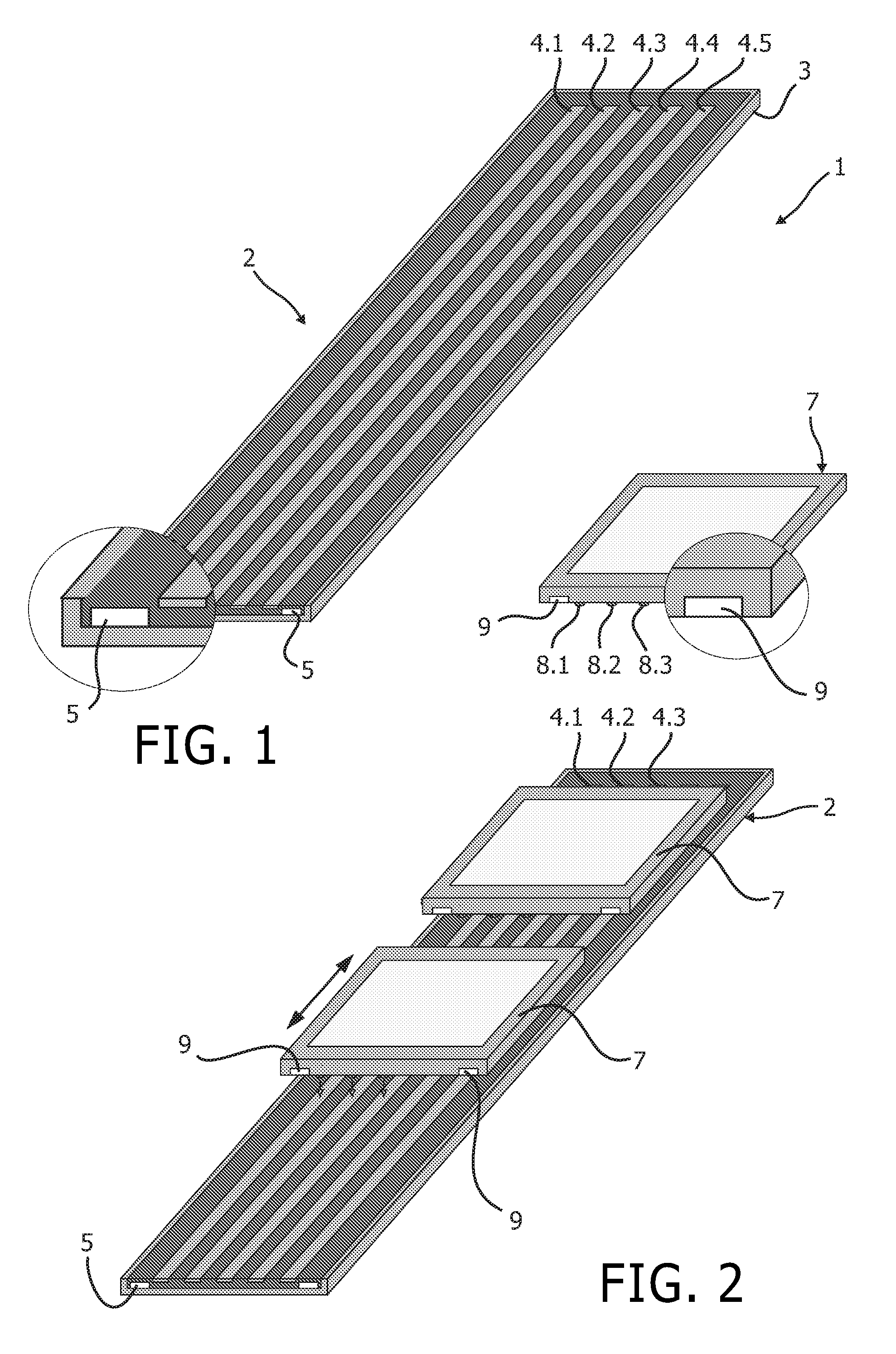
[0033]In FIG. 1, a modular electric system is schematically shown and indicated with reference numeral 1. The system comprises a base module 2, which forms the fixed part of the system, and at least one load module 7, which forms the freely placeable and removable part of the system. The base module 2 comprises a base plate 3, which may be provided as a substrate carried by a frame. The substrate, which may e.g. include a printed circuit board and / or an assembly of several layers made of the same or different materials and shapes, comprises at least two electrodes, e.g. in the form of elongated parallel conductor lines extending along the whole length of the substrate. The substrate may also consist of multiple parts, such as case, mounting fixtures, mechanical stabilizers, etc. The electrodes, which are indicated with reference numerals 4.1-4.5 in FIG. 1, are provided to supply power to the load modules and to transmit data between the base module and the load modules.

[0034]Further...


PUM


Abstract

The present invention relates to a modular electric system with a base module (2, 11) comprising a substrate (3, 12), a power supply (40), power / data transmission means (4, 16) and holding means; at least one load module (7, 20, 30) comprising an cc electric load, a power / data receiving means (8, 26) and a holding means, said load module (7, 20, 30) being adapted to be placeable on said substrate (3, 12) in first and second positions, wherein in said first position (connecting position) the transmission means (4, 16) of said base module interact with said receiving means (8, 26) of said load module (7, 20, 30) and in said second position (repelling position) interaction of said transmission means (4, 16) and said receiving means (26) is not allowed or possible. The modular electric system is characterized in that said holding means of said base module and said load module comprise magnet elements (5, 9, 49, 59) which are arranged relative to each other such that the load module (7, 20, 30) is removably held in said first position and is not held in said second position.

Description

FIELD OF THE INVENTION[0001]The present invention relates to a modular electric system with a base module comprising a substrate, a power supply, power / data transmission means and holding means; at least one load module comprising an electric load, a power / data receiving means and a holding means, said load module being adapted to be placeable on said substrate in first and second positions, wherein in said first position the transmission means of said base module interact with said receiving means of said load module and in said second position interaction of said transmission means and said receiving means is not allowed or possible.BACKGROUND OF THE INVENTION[0002]In many applications, it is desired that products are scaleable. This means that the products consist of multiple parts, some or all of which are removable. For correct positioning, mechanical connectors, such as screws, tags or snap-on connections are required. These connectors, however, encounter several problems. For...

Claims


Application Information

Patent Timeline
IPC IPC(8): H05K7/00
CPCF21V21/096F21Y2105/008F21V23/02H01L25/048H01L27/3293H01L51/5203H01L2251/5361H01R13/6205H01R25/147H05B33/0896H05B37/0254H05B39/00H05K3/303H05K3/325H05K2201/083H05K2201/10106H05K2203/168F21Y2101/02F21Y2105/001F21V21/34F21Y2113/00H01L2924/0002F21Y2105/00F21Y2105/10F21Y2115/10F21Y2115/15H01R13/64H05B45/60H05B47/18Y02B20/30Y02P70/50H10K59/90H10K59/18H10K59/805H01L2924/00H10K50/805
Inventor JACOBS, JOSEPH H.A.M.HENTE, DIRKWAFFENSCHMIDT, EBERHARDT
Owner SIGNIFY HLDG BV
Learn More