Focusing control device, imaging device, focusing control method, and focusing control program

a technology of focusing control and imaging device, which is applied in the direction of focusing aids, instruments, television systems, etc., can solve the problems of incorrect focusing position determination and deterioration of focusing accuracy, and achieve the effect of high accuracy

Active Publication Date: 2018-08-02
FUJIFILM CORP
View PDF3 Cites 3 Cited by
  • Summary
  • Abstract
  • Description
  • Claims
  • Application Information

AI Technical Summary

Benefits of technology

The invention relates to a focusing control device for an imaging device that can accurately focus on subjects with low frequency or low contrast. The device uses evaluation values to determine the focusing position of the focus lens, which can be calculated based on image signals captured by the imaging element. The device selectively calculates a maximum point of the evaluation value curve to determine the optimal focusing position, and performs focusing control to move the focus lens to the determined position. The device can also determine the sharpness of the evaluation value curve to ensure accurate focusing. The technical effect of this invention is to increase the accuracy of focusing on low-contrast subjects, improving the overall quality of the captured images.

Problems solved by technology

In a case where the shape of the evaluation value curve is gentle, since calculation accuracy of the approximate curve of the evaluation value curve deteriorates, there is a high possibility that the focusing position will be incorrectly determined.
However, since the calculation accuracy of the polynomial approximate curve deteriorates as stated above in a case where a subject having low contrast is captured, the focusing accuracy deteriorates.

Method used


Image

  • Focusing control device, imaging device, focusing control method, and focusing control program
  • Focusing control device, imaging device, focusing control method, and focusing control program
  • Focusing control device, imaging device, focusing control method, and focusing control program

Examples


first modification example

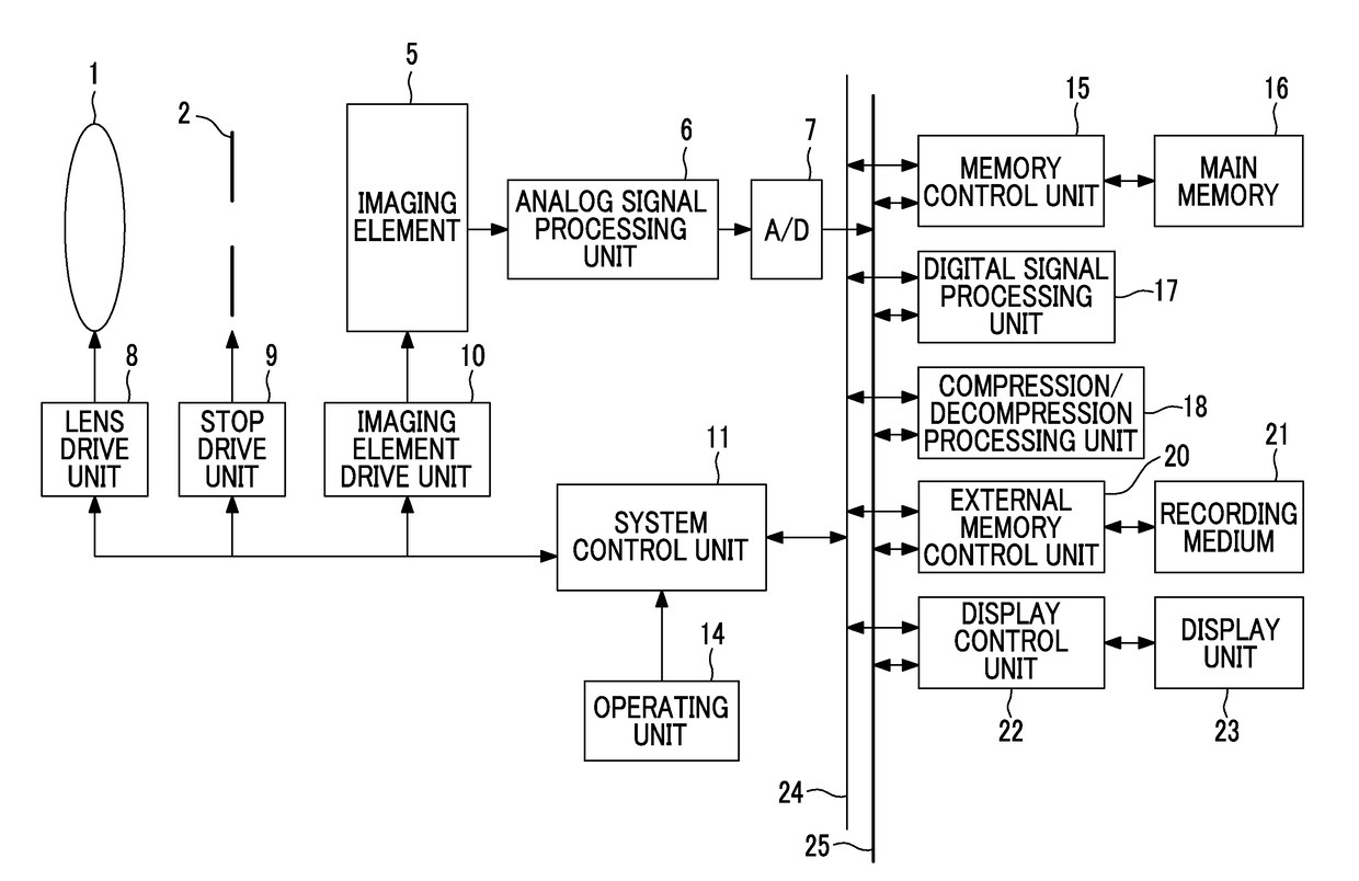
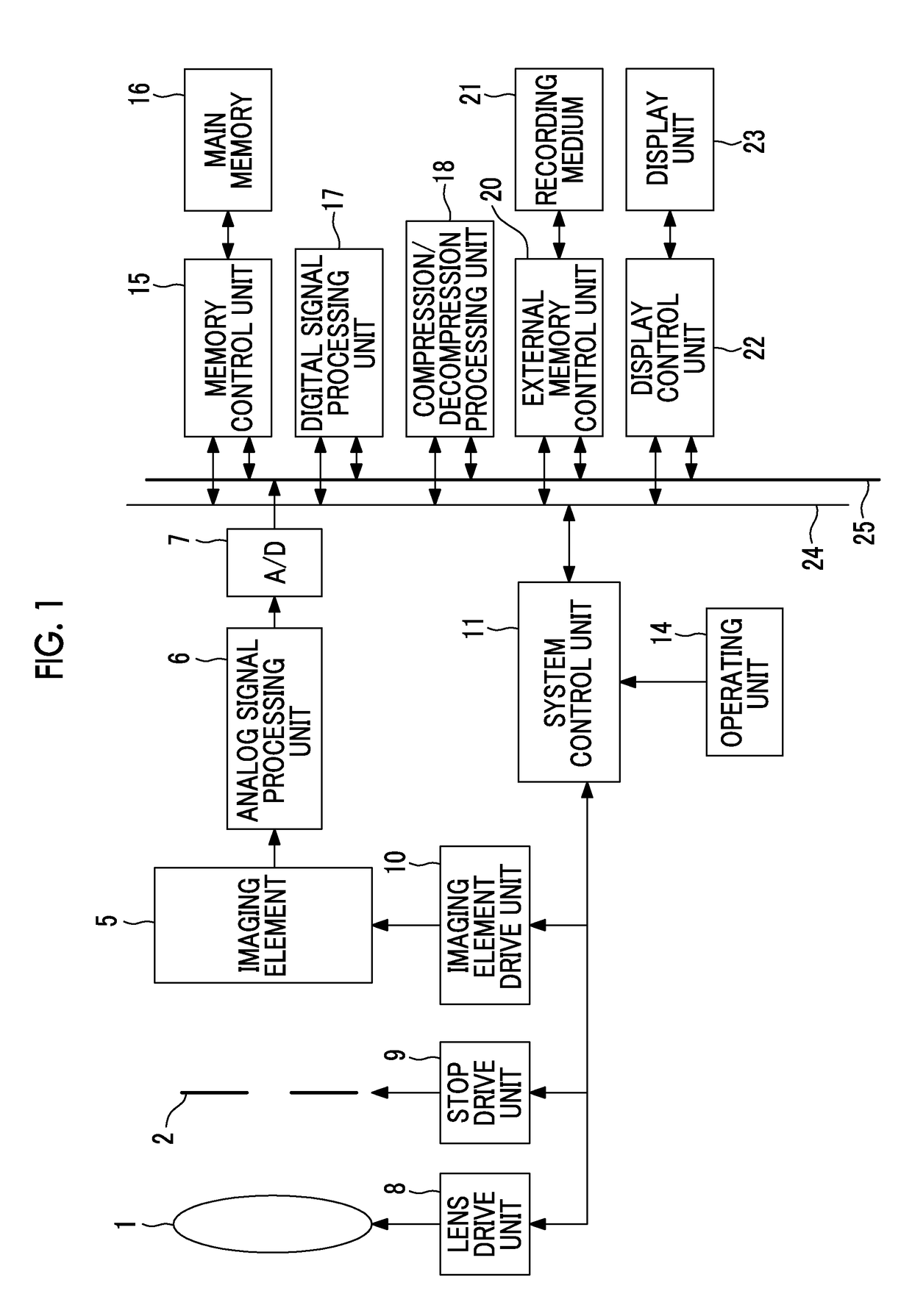
[0107]FIG. 6 is a functional block diagram showing a modification example of the system control unit 11 of the digital camera of FIG. 1. A sharpness determination unit 194 is newly added to the system control unit 11 shown in FIG. 6, and other functional blocks are basically the same as those shown in FIG. 2.

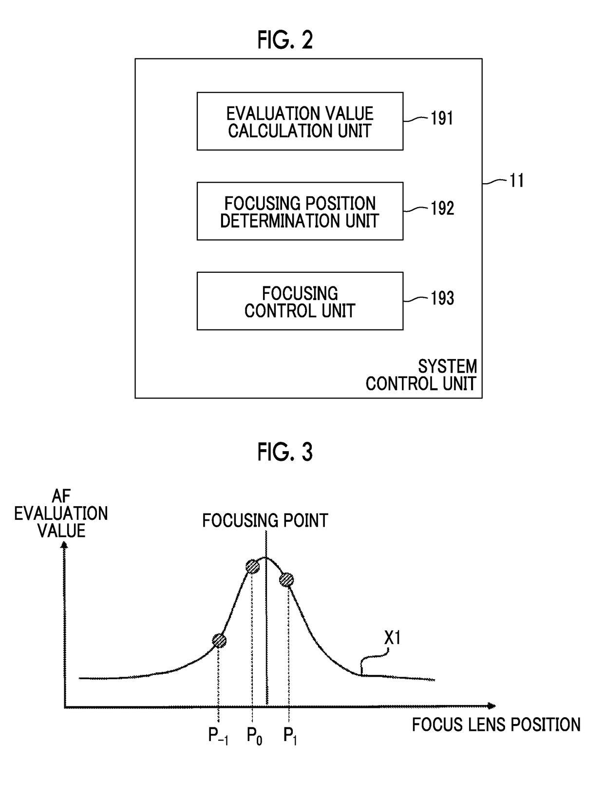
[0108]The sharpness determination unit 194 determines sharpness of a curve (hereinafter, referred to as a determination evaluation value curve) indicating the relationship between the movement range and the AF evaluation values corresponding to a predetermined movement range of the focus lens including the evaluation value maximum position in which the maximum AF evaluation value is acquired among the AF evaluation values calculated by the evaluation value calculation unit 191 based on the AF evaluation values corresponding to the predetermined movement range.

[0109]As the shape of the AF evaluation value curve near the peak is elongated toward the peak as described in FIGS. 3 an...

second modification example

[0132]It has been described above that a difference between the distributions of the AF evaluation values is generated even for the same subject by changing the filtering process as shown in FIGS. 3 and 4. However, even though the same filtering process is used, a difference between the distributions of the AF evaluation values may be generated in certain spatial frequency or contrast of the subject as shown in FIGS. 3 and 4.

[0133]For example, in a case where one kind of filtering process is fixed as the filtering process performed by the evaluation value calculation unit 191, the distribution of the AF evaluation values shown in FIG. 4 may be acquired in a case where the subject having low spatial frequency or contrast is captured, and the distribution of the AF evaluation values shown in FIG. 3 may be acquired in a case where the subject having high spatial frequency or contrast is captured.

[0134]Accordingly, even in this case, the changing of the number of AF evaluation values us...

third modification example

[0143]In the digital camera of FIG. 1, the digital camera according to the first modification example, and the digital camera according to the second modification example, the focusing position determination unit 192 controls the number of AF evaluation values used in the calculation of the maximum point of the AF evaluation value curve based on the sharpness of the determination evaluation value curve or the passband in the selected filtering process.

[0144]In a case where the function of multiple orders or more or the Gaussian function is used in the calculation of the AF evaluation value curve, as a shape of a curve (hereinafter, referred to as a data curve) indicating the relationship between the AF evaluation values selected by the focusing position determination unit 192 and the focus lens positions corresponding to the AF evaluation values is symmetric with respect to the evaluation value maximum position or as the shape of the curve is convex in a direction in which the evalu...


PUM


Abstract

A focusing control device includes: an evaluation value calculation unit that causes an imaging element which images a subject through a focus lens to image the subject for each of positions of the focus lens while moving the focus lens movable in an optical axis direction, and calculates evaluation values for determining a focusing position of the focus lens based on signals acquired by performing any filtering process selected among a plurality of filtering processes in which passbands are different on captured image signals acquired through the imaging; a focusing position determination unit as defined herein; and a focusing control unit that performs focusing control to move the focus lens to the focusing position, and the focusing position determination unit increases number of the selected evaluation values as a lower frequency limit of the passband becomes lower, as the filtering process selected by the evaluation value calculation unit.

Description

CROSS REFERENCE TO RELATED APPLICATION[0001]This is a continuation of International Application No. PCT / JP2016 / 066299 filed on Jun. 1, 2016, and claims priority from Japanese Patent Application No. 2015-194232 filed on Sep. 30, 2015, the entire disclosures of which are incorporated herein by reference.BACKGROUND OF THE INVENTION1. Field of the Invention[0002]The present invention relates to a focusing control device, an imaging device, a focusing control method, and a computer readable medium storing a focusing control program.2. Description of the Related Art[0003]In recent years, with an increase in resolution of imaging elements, such as a charge coupled device (CCD) image sensor and a complementary metal oxide semiconductor (CMOS) image sensor, there is a rapid increase in demand for information devices having an imaging function, such as a digital still camera, a digital video camera, and a smartphone. The information devices having an imaging function described above are refer...

Claims


Application Information

Patent Timeline
IPC IPC(8): G02B7/36G03B13/36H04N5/232
CPCG02B7/36G03B13/36H04N5/23212H04N23/673H04N23/62G06F3/00
Inventor TANAKA, KOICHI
Owner FUJIFILM CORP
Why Eureka
Try Eureka