Driving apparatus for electric motor

a technology for driving apparatuses and electric motors, applied in the direction of dynamo-electric converter control, dynamo-electric gear control, etc., can solve the problems of poor feedback information of control, inability to adapt high-efficiency control for individual motor characteristics, and rotor of synchronous motors can lose synchronization. , to achieve the effect of driving

Active Publication Date: 2017-03-09
EBARA CORP
View PDF5 Cites 7 Cited by
  • Summary
  • Abstract
  • Description
  • Claims
  • Application Information

AI Technical Summary

Benefits of technology

The present invention allows for a driving apparatus to output an inverter output voltage that changes based on the load on the motor. This is achieved by determining the target output voltage from a combination of torque current, magnetization current, angular velocity of the rotor, and motor constants. This results in a more efficient and effective driving of the motor.

Problems solved by technology

However, the V / F control is poor in feedback information, and therefore high-efficiency control adapted for characteristics of each individual motor cannot be expected.
Furthermore, since the V / F control does not detect a position of a motor rotor, a rotor of a synchronous motor can lose synchronism.
As a result, an operation efficiency of the motor is lowered in a low-load speed range, while the motor rotor can lose synchronism in a high-load speed range, making it difficult to achieve a stable control.

Method used


Image

  • Driving apparatus for electric motor
  • Driving apparatus for electric motor
  • Driving apparatus for electric motor

Examples


Embodiment Construction

[0037]Embodiments of the present invention will now be described with reference to the drawings.

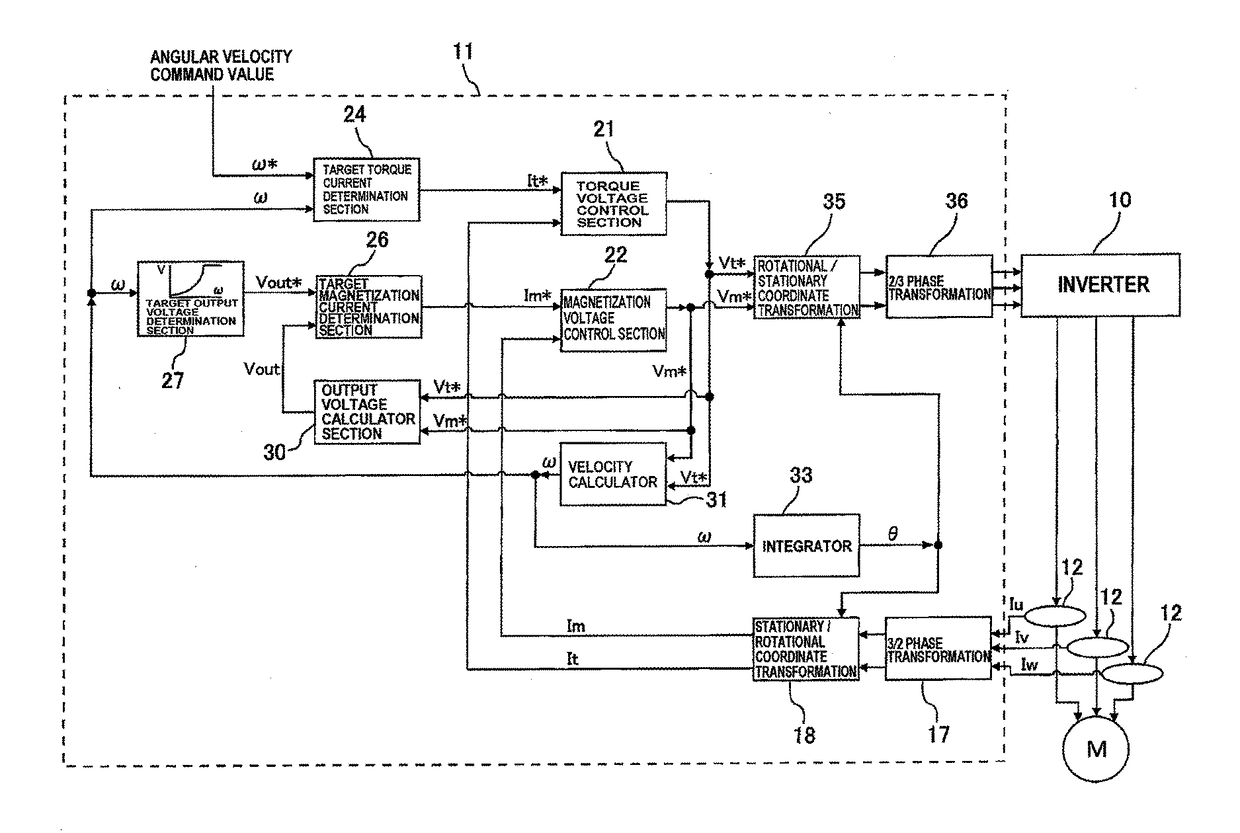
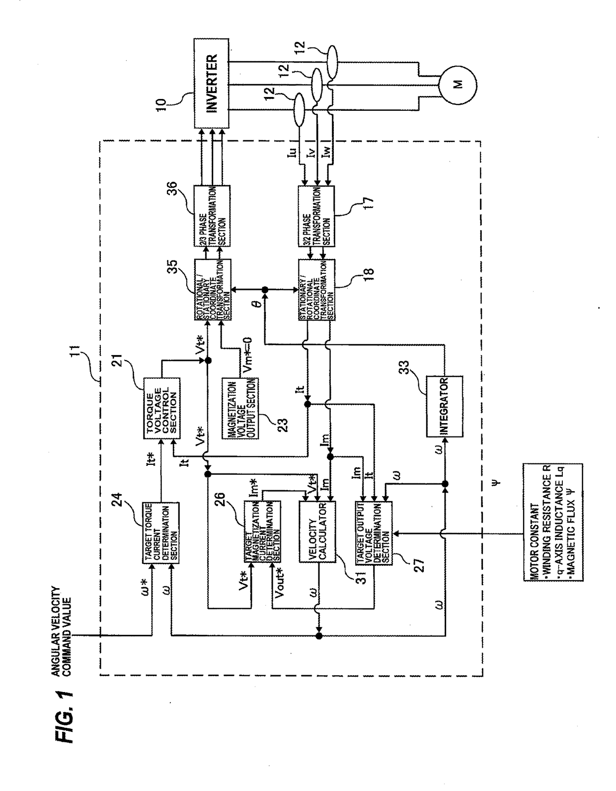
[0038]FIG. 1 is a block diagram showing a driving apparatus according to an embodiment of the present invention. This driving apparatus is an inverter device (or power conversion device) for driving a motor M. As shown in FIG. 1, the driving apparatus is constituted by a plurality of elements including an inverter 10 and a vector controller 11. Specifically, the driving apparatus includes the inverter 10 for generating a voltage to be supplied to the motor M, the vector controller 11 for determining a voltage command value for the inverter 10, and a current detector (or an ammeter) 12 for detecting an electric current supplied from the inverter 10 to the motor M.

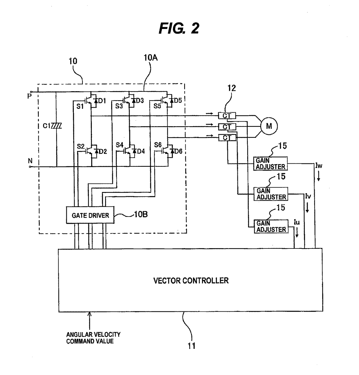
[0039]FIG. 2 is a schematic diagram showing a detail of the inverter 10 shown in FIG. 1. The inverter 10 is basically constituted by an inverter circuit 10A as a power converter, and a gate driver 10B for driving the inverter circ...


PUM


Abstract

A driving apparatus for driving an electric motor, such as a synchronous motor or an induction motor, and more particularly to a driving apparatus which performs a vector control based on an output current of an inverter. The driving apparatus of the present invention includes an inverter, a current detector configured to detect an output current of the inverter, and a vector controller configured to transform the output current, detected by the current detector, into a torque current and a magnetization current and to control the torque current and the magnetization current. The vector controller includes a target-output-voltage determination section configured to determine a target output voltage from the torque current, the magnetization current, an angular velocity of the rotor, and motor constants, and a target-magnetization-current determination section configured to determine a magnetization-current command value based on a deviation between the torque-voltage command value and the target output voltage.

Description

TECHNICAL FIELD[0001]The present invention relates to a driving apparatus for driving an electric motor, such as a synchronous motor or an induction motor, and more particularly to a driving apparatus which performs a vector control based on an output current of an inverter.BACKGROUND ART[0002]Commonly-used conventional methods for controlling a motor include a V / F control which involves outputting a voltage corresponding to a command frequency, thereby keeping a motor magnetic flux constant, and a vector control which involves decomposing an inverter output current into an excitation current and a torque current, and controlling the excitation voltage and the torque voltage so as to generate a motor current which is commensurate with a load.[0003]The V / F control does not require a high-speed computation and can control a motor with a simple construction. However, the V / F control is poor in feedback information, and therefore high-efficiency control adapted for characteristics of ea...

Claims


Application Information

Patent Timeline
Patent Type & Authority Applications(United States)
IPC IPC(8): H02P21/24H02P6/18H02P27/08
CPCH02P21/24H02P6/18H02P27/08H02P21/00
Inventor TSUKAKOSHI, KENTAKOMAI, MASAKAZU
Owner EBARA CORP
Why Eureka
Try Eureka