
Middle/high carbon steel sheet and method for manufacturing same

a high carbon steel and middle/high carbon steel technology, applied in manufacturing tools, heat treatment equipment, furnaces, etc., can solve the problems of not always providing the desired effect, revealing anything about knowledge and techniques, and reducing the area of the reduction, so as to achieve excellent workability, favorable deep drawability, and excellent reduction in size

Inactive Publication Date: 2017-03-09
NIPPON STEEL CORP
View PDF6 Cites 1 Cited by
  • Summary
  • Abstract
  • Description
  • Claims
  • Application Information

AI Technical Summary

Benefits of technology

The technical effects of the patent text are that various methods and techniques are disclosed for manufacturing high carbon steel with excellent properties such as deep drawability, workability, reduction in size, formability, and high strength or wear resistance. These methods involve controlling the structure of steel products through finishing rolling, annealing, and other processes, which can improve material quality and reduce areas of the steel sheet. Additionally, the patent text references other prior art documents that further enhance the understanding and development of these techniques.

Problems solved by technology

However, the technique disclosed by Patent Document 1 is a technique in which reduction in area is increased by improving the roughness of the steel sheet surface, but is not a technique in which reduction in area is increased by improving material quality by the control of the structure forms of steel products and thus does not always provide the desired effects of the invention.
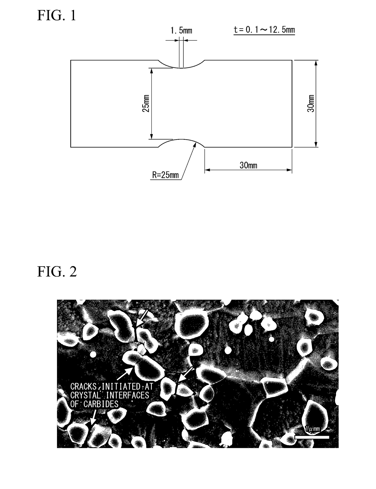
However, none of the above-described patent documents discloses anything about knowledge and techniques that suppress the cracking of cementite in steel products, which occurs during shaping at a high strain rate, and a decrease in reduction in area caused by the growth and joining of voids initiated due to the initiation of cracks.

Method used


Image

  • Middle/high carbon steel sheet and method for manufacturing same
  • Middle/high carbon steel sheet and method for manufacturing same

Examples


Embodiment Construction

[0118]Next, the effects of the present invention will be described using examples.

[0119]The levels of the examples are examples of conditions for carrying out the present invention which were employed to confirm the feasibility and effects of the present invention, and the present invention is not limited to these condition examples. The present invention allows employment of a variety of conditions within the scope of the gist of the present invention as long as the object of the present invention is achieved.

[0120]Continuous cast pieces (steel ingots) having a composition shown in Table 1 were heated at 1,140° C. for 1.6 hours and then were hot-rolled, thereby obtaining 250 mm-thick slabs. The slabs were roughly hot-rolled to a thickness of 40 mm, rough bars, which are materials for finishing hot-rolling, were heated by 36° C. so as to initiate finish hot-rolling, the rough bars were finishing-hot-rolled at 880° C., then, were cooled to 520° C. on ROT at a cooling rate of 45° C. / s...


PUM

PropertyMeasurementUnit
temperatureaaaaaaaaaa

Abstract

A middle / high carbon steel sheet according to an aspect of the present invention is a steel sheet, in which composition thereof contains, by mass %, C: 0.10% to 1.50%, Si: 0.01% to 1.00%, Mn: 0.01% to 3.00%, P: 0.0001% to 0.1000%, and S: 0.0001% to 0.1000%, and a remainder consisting of Fe and impurities, in which the steel sheet has a structure in which a total volume percentage of a martensite, a bainite, a pearlite, and a residual austenite is equal to or lower than 5.0%, and a remainder thereof is a ferrite and carbides, in which a spheroidizing ratio of carbide particles is 70% to 99%, and in which a proportion of a number of the carbide particles including a crystal interface at which an orientation difference is equal to or greater than 5° in the carbide particles is equal to or lower than 20% of a total number of the carbide particles.

Description

TECHNICAL FIELD OF THE INVENTION[0001]The present invention relates to a middle / high carbon steel sheet exhibiting excellent reduction in area during shaping at a high strain rate and a method for manufacturing the same.[0002]The present application claims priority on the basis of Japanese Patent Application No. 2014-045689, filed on Mar. 7, 2014, the content of which is incorporated herein.RELATED ART[0003]Middle / high carbon steel sheets are used as materials for drive system components such as chains, gears, and clutches in vehicles, saws, blades, and the like. Materials obtained by shaping steel strips of middle / high carbon steel or steel sheets cut out from the steel strips into predetermined shapes are shaped into component shapes by deformation processing such as deep drawing, hole expanding, thickening, or thinning. In cold forging in which each of processes is individually carried out or processes of multiple kinds are carried out at the same time, materials are partially sh...

Claims


Application Information

Patent Timeline
Patent Type & Authority Applications(United States)
IPC IPC(8): C21D9/46C22C38/32C22C38/16C22C38/14C21D8/02C22C38/08C22C38/06C22C38/04C22C38/02C22C38/00C22C38/60C22C38/12
CPCC21D9/46C21D2211/009C22C38/32C22C38/16C22C38/14C22C38/12C22C38/08C22C38/06C22C38/04C22C38/02C22C38/008C22C38/005C22C38/002C22C38/001C21D8/0226C21D8/0236C21D8/0263C21D2211/001C21D2211/002C21D2211/008C22C38/60C21D1/32C21D8/0473C21D2201/05C21D2211/003C21D2211/004C21D2211/005C21D9/48
Inventor TAKEDA, KENGOTOMOKIYO, TOSHIMASATSUKANO, YASUSHIARAMAKI, TAKASHI
Owner NIPPON STEEL CORP
Learn More