
Plasma etching method, pattern forming method and cleaning method

a technology of etching method and cleaning method, which is applied in the field of etching method and pattern forming method, and cleaning method, can solve the problems of difficult formation of deep and vertical holes and trenches into the target film to be etched, and the etching properties become wors

Active Publication Date: 2016-10-13
TOKYO ELECTRON LTD
View PDF8 Cites 0 Cited by
  • Summary
  • Abstract
  • Description
  • Claims
  • Application Information

AI Technical Summary

Benefits of technology

The present invention provides a method to selectively etch a film, such as a zirconium oxide film, using plasma generated from a first gas. The gas includes at least one chloride-containing gas and at least one hydrogen-containing gas. The etching selectivity of the zirconium oxide film to an underlying film (e.g. silicon oxide or amorphous carbon film) is greater than or equal to 1. This allows for efficient and selective etching of zirconium oxide films without compromising the integrity of the underlying film.

Problems solved by technology

However, when etching selectivity of the target film to be etched, such as the high-k film, to an underlying film cannot be sufficiently obtained, forming the deep and vertical holes and trenches into the target film to be etched becomes difficult, and the etching properties become worse.

Method used


Image

  • Plasma etching method, pattern forming method and cleaning method
  • Plasma etching method, pattern forming method and cleaning method
  • Plasma etching method, pattern forming method and cleaning method

Examples


experiment 1

[0038]( Gas Species for Zirconium Oxide Film: Single Gas)

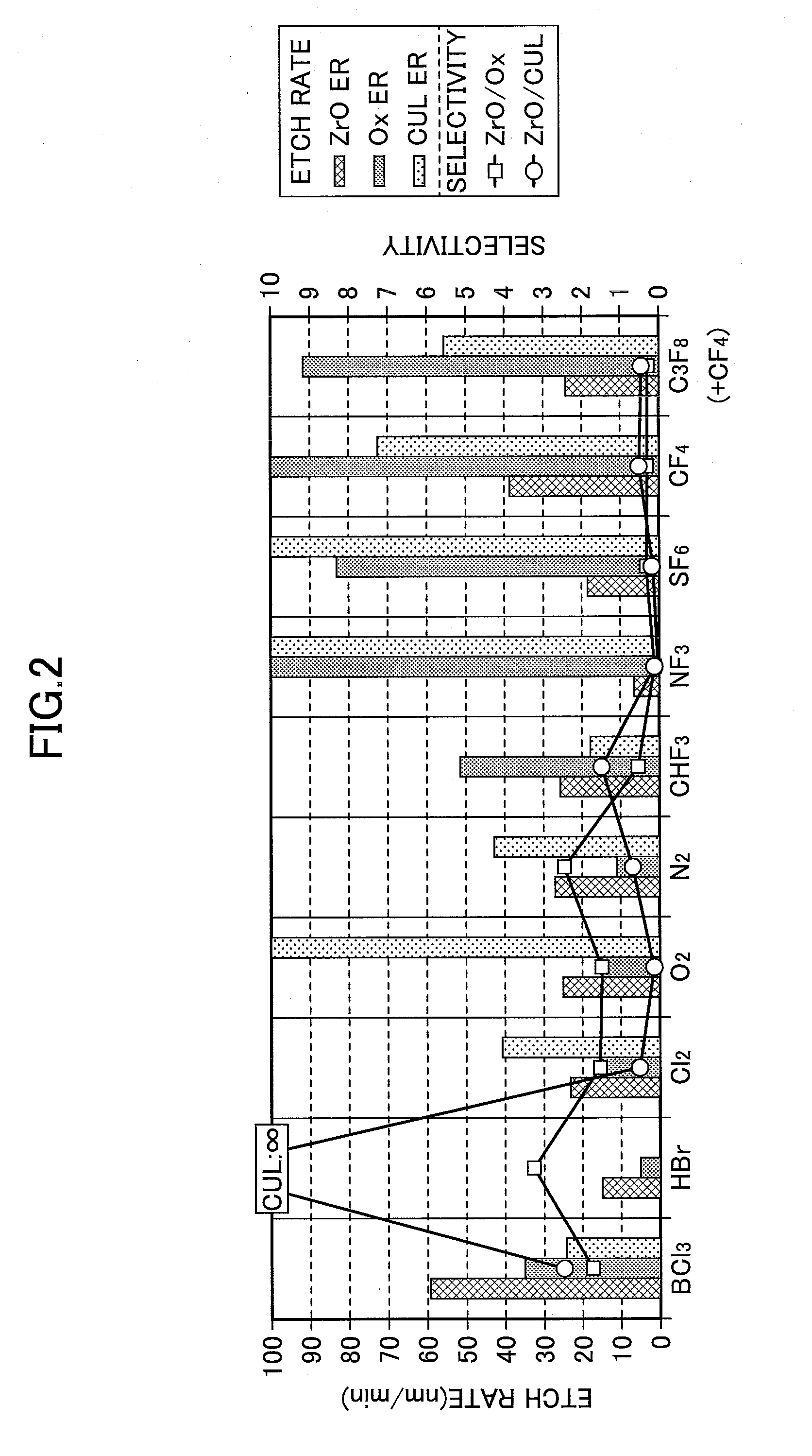
[0039]FIG. 2 shows an experimental result of an etching rate (ETCH RATE) and selectivity (SELECTIVITY) when performing the plasma etching on a zirconium oxide film (ZrO), a silicon oxide film (SiO2) and an amorphous carbon film (α-C) when using a plurality of gas species.

[0040]In FIG. 2, and FIGS. 3 through 7 described later, a silicon oxide film of an example of a target film to be etched is expressed as an “Ox,” and an amorphous carbon film of another example of a target film to be etched is expressed as a “CUL.” Also, a “ZrO ER”, an “Ox ER” and a “CUR ER” express etching rates of the zirconium oxide film, the silicon oxide film and the amorphous carbon film, respectively. Moreover, a “ZrO / Ox” expresses selectivity of the zirconium oxide film to the silicon oxide film (which is hereinafter referred to as the selectivity “ZrO / Ox”). A “ZrO / CUL” expresses selectivity of the zirconium oxide film to the amorphous carbon film (whi...

experiment 3

[0049]( Gas Species for Zirconium Oxide Film: Proportion of BCl3, HBr and H2)

[0050]Next, a plasma etching process in which the ratio between hydrogen bromide (HBr) and hydrogen (H2) is varied, while the flow rate of boron trichloride (BCl3) is fixed, was evaluated. FIG. 4 shows the experimental results. In the experiment, the plasma etching process was performed by changing the ratio between hydrogen bromide (HBr) and hydrogen (H2) while setting the flow rate of boron trichloride (BCl3) at “125 sccm.” A proportion of three of the gases is shown in the horizontal axis, and an etching rate is shown in the vertical axis. The ratio of hydrogen (H2) to hydrogen bromide (HBr) increases toward the right side of the graph.

[0051]The results indicated that the selectivity “ZrO / Ox” and the selectivity “ZrO / CUL” basically increased when hydrogen bromide (HBr) was displaced by hydrogen (H2) in this manner. In particular, the selectivity “ZrO / Ox” increased as hydrogen bromide (HBr) was displaced ...


PUM


Abstract

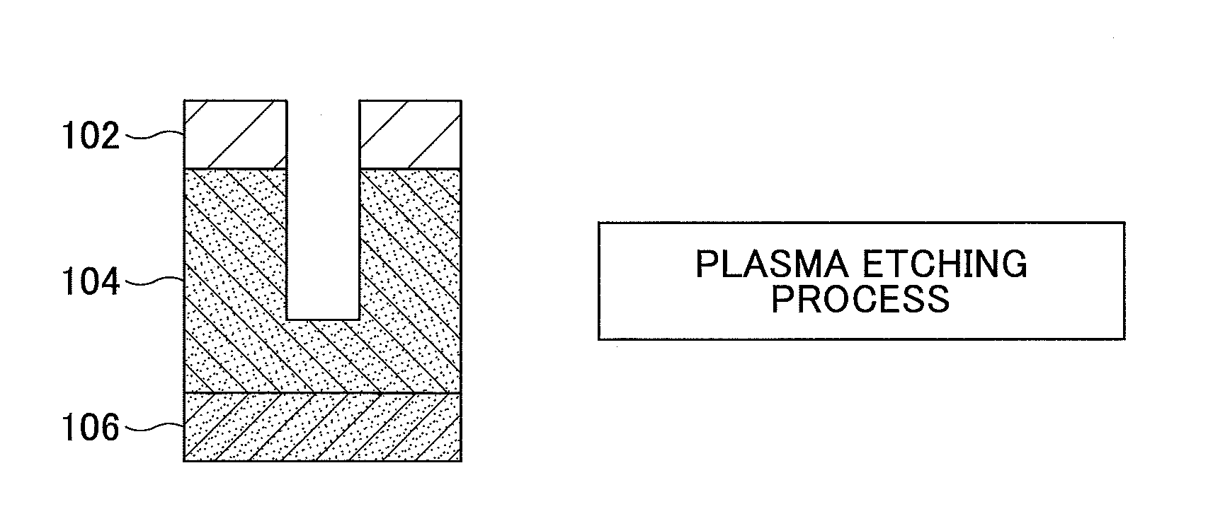
A plasma etching method is performed by forming a desired pattern of a mask into a film including a zirconium oxide film by plasma etching with plasma generated from a first gas. The first gas consists of at least one chloride-containing gas of the group of boron trichloride, tetrachloromethane, chloride and silicon tetrachloride, at least one hydrogen-containing gas of the group of hydrogen bromide, hydrogen and methane, and a noble gas. An underlying film of a silicon oxide film or an amorphous carbon film is provided underneath the zirconium oxide film, and an etching selectivity of the zirconium oxide film to the underlying film is greater than or equal to one.

Description

CROSS-REFERENCE TO RELATED APPLICATIONS[0001]This patent application is based upon and claims the benefit of priority of Japanese Patent Application No. 2015-81019, filed on Apr. 10, 2015, the entire contents of which are incorporated herein by reference.BACKGROUND OF THE INVENTION[0002]1. Field of the Invention[0003]The present invention relates to a plasma etching method, a pattern forming method and a cleaning method.[0004]2. Description of the Related Art[0005]A technique is known of finely processing a target film to be etched by a plasma etching by generating plasma from a gas. For example, Japanese Laid-Open Patent Application Publication No. 2005-252186 discloses a technique of depositing a silicon oxide film on a substrate by a thermal oxidation process first, then depositing a high-k (high-dielectric-constant) film on the silicon oxide film by CVD (Chemical Vapor Deposition), and etching the high-k film by using plasma generated from a gas such as Cl2. Also, Japanese Laid-...

Claims


Application Information

Patent Timeline
IPC IPC(8): H01L21/311B08B9/08H01L21/32B08B7/00H01L21/02H01L21/67
CPCH01L21/31122H01L21/31144H01L21/02189B08B9/08H01L21/32B08B7/0035H01L21/67069C01B9/04C01B33/1071C01B35/061H01L21/02046H01L21/02315H01L21/3065H01L21/32136H01L21/32137H01L21/02334H01L21/0234H01L21/311H01C17/003H01C17/2416
Inventor MIKAMI, SHUNICHI
Owner TOKYO ELECTRON LTD
Learn More