
Production of polymeric particles and rough coatings by ink jet printing

a technology of ink jet printing and polymeric particles, which is applied in the direction of coatings, manufacturing tools, and applying layer means, etc., can solve the problems of not being able to specifically apply to the surface, the conductivity of magnetic properties of coatings can also be affected by the use of particles, and achieves minimal adhesion to one, minimal adhesion to the substrate, and reduced porosity

Active Publication Date: 2016-09-01
ACTEGA SCHMID RHYNER AG
View PDF1 Cites 5 Cited by
  • Summary
  • Abstract
  • Description
  • Claims
  • Application Information

AI Technical Summary

Benefits of technology

The invention is about using ink jet technology to apply particles. It makes use of the fact that ink jet technology allows particles to be applied in a specific way by digital activation of nozzles. The invention also suggests using a pulsed laser or a pulse laser, which can lead to quick curing of the particles during droplet flight because of the high light intensity achieved through pulsed layers. This results in improved efficiency in the application process.

Problems solved by technology

In addition, this obviates the need for the aforementioned additives.
A drawback of this method is that the particles are homogenously distributed in the coating material and therefore cannot specifically be applied to the surface.
Moreover, the conductivity of magnetic properties of coatings can also be affected by the use of particles.
Materials representing of all the above-mentioned particle types exert their action based on a specified particle size, with the result that they cannot be produced in any desired small size.
In using ink jets, there are limits on the use of particles due to the small jet diameter, which is in the micron range.
Excessively large particles can block the nozzles and thus potentially destroy the ink jet head.
In addition to this risk, particles having diameters larger than the nozzle diameter cannot be processed by ink jet methods.

Method used


Image

  • Production of polymeric particles and rough coatings by ink jet printing
  • Production of polymeric particles and rough coatings by ink jet printing
  • Production of polymeric particles and rough coatings by ink jet printing

Examples


Embodiment Construction

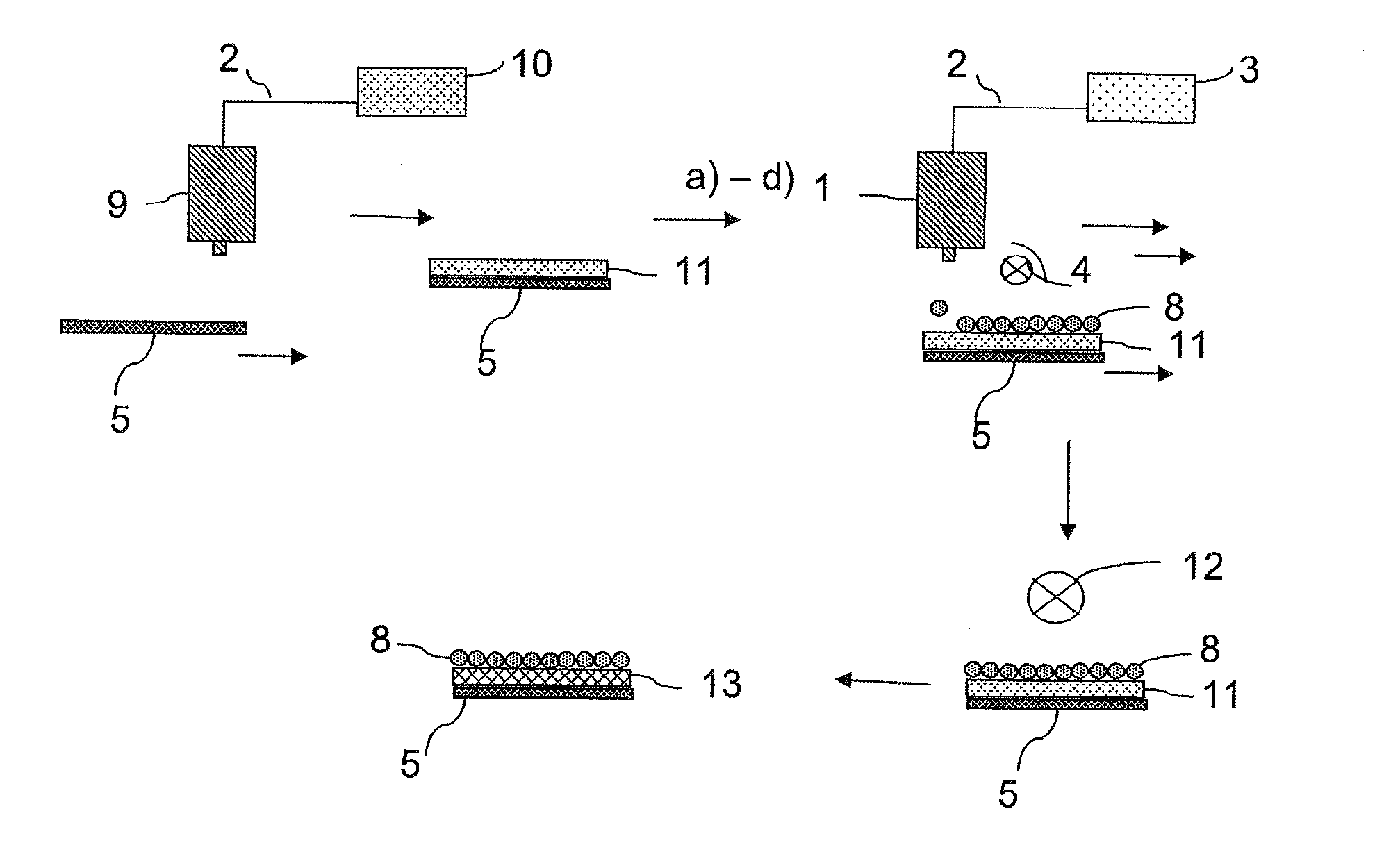
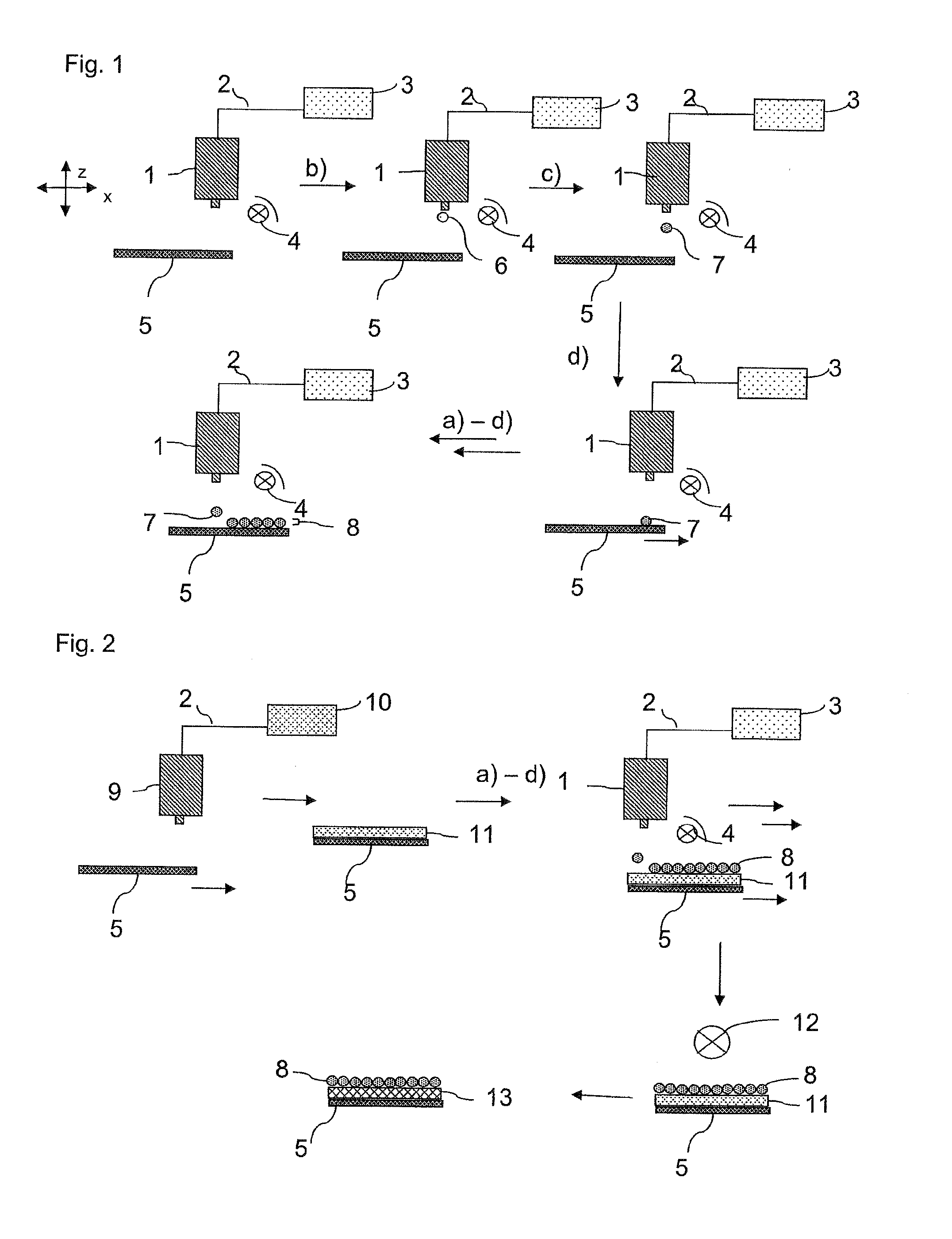
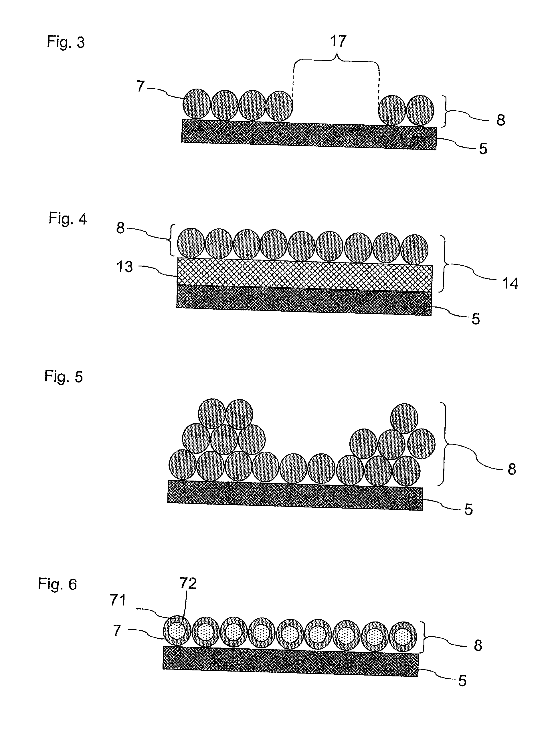
[0104]FIG. 1 shows a schematic representation of an embodiment of the production method according to the invention in which the partially cured particles 7 are deposited as a rough coating 8 on a substrate 5. For this purpose, a substrate 5 is first prepared. The substrate is positioned at a fixed interval below an ink jet print head 1 which is connected via a line 2 to a reservoir 3 containing the fluid preparation for processing with ink jet nozzles. Moreover, a light source 4 is positioned in such a way that the radiation emitted from the light source 4 is incident on the interval between the print head 1 and substrate 5 (step a). The print head 1 ejects the fluid preparation for processing with ink jet nozzles in the form of individual droplets 6 that fall onto the substrate 5 (step b). During the flight of the droplet 6 through the radiation emitted by the light source 4, it is at least partially cured (step c), so that the at least partially cured droplets or particles 7 strik...


PUM

PropertyMeasurementUnit
Timeaaaaaaaaaa
Fractionaaaaaaaaaa
Volumeaaaaaaaaaa

Abstract

A method for producing polymer particles is disclosed in which a fluid preparation is ejected in drop form from a nozzle of an ink jet print head. At least one nozzle ejects droplets in response to electrical signals, and radiation from a radiation source is directed on the droplets in flight, whereby the fluid preparation is at least partially cured by irradiation, so that particles are obtained from the fluid drops before impact or collection. The fluid preparation contains a prepolymer, an oligomer, monomers, or reactive diluents as well as at least one photoinitiator. The fluid preparation has a polymerizable group that is radically polymerizable. Further, a printed product and a device for making the printed product are disclosed. The printed product has a rough polymeric coating that is composed of spherical or largely spherically shaped polymer particles.

Description

CROSS REFERENCE TO RELATED APPLICATIONS[0001]This application is a continuation application of international patent application PCT / EP2014 / 074287, filed Nov. 11, 2014, designating the United States and claiming priority from German application 10 2013 112 404.6, filed Nov. 12, 2013, and the entire content of both applications is incorporated herein by reference.FIELD OF THE INVENTION[0002]The invention generally concerns a method for producing polymer particles and polymeric structures composed of thermoplastics and / or elastomers and / or duromers, referred to in the following as particles or polymer particles. In particular, the invention concerns a method for producing rough polymeric coatings, a printed product comprising a substrate or carrier material with at least one rough polymeric coating, and a corresponding device for producing rough polymeric coatings on a substrate or carrier material.BACKGROUND OF THE INVENTION[0003]Methods for producing three-dimensional structures on a...

Claims


Application Information

Patent Timeline
IPC IPC(8): B41M5/50B41J2/01B41J11/00
CPCB41M5/502B41J2/01B41J11/0015B05D5/02B41J11/00214B33Y10/00B33Y30/00B29C64/112B33Y70/10B33Y70/00B29C64/209B05D3/067B41J2/135C08J3/12C08J3/28
Inventor SCHLATTERBECK, DIRK
Owner ACTEGA SCHMID RHYNER AG
Learn More