Supercharge Your Innovation With Domain-Expert AI Agents!

Cover plate with intruding feature to improve al-steel spot welding

Inactive Publication Date: 2015-12-10
GM GLOBAL TECH OPERATIONS LLC
View PDF3 Cites 26 Cited by
  • Summary
  • Abstract
  • Description
  • Claims
  • Application Information

AI Technical Summary

Benefits of technology

The patent text describes a method of spot welding that uses a cover plate with an intruding feature to improve the solidification of the weld pool and reduce defects. The cover plate can be made of a more thermally resistive material than the aluminum alloy workpiece to further promote solidification. The method allows for flexible welding electrode designs that can be used with different workpiece stack-ups without the need for a substitute. The technical effects include improved weld joint mechanical properties and more desirable solidification behavior.

Problems solved by technology

In practice, however, spot welding a steel workpiece to an aluminum alloy workpiece is challenging since a number of characteristics of those two metals can adversely affect the strength—most notably the peel strength—of the weld joint.
As a result of their physical properties, the refractory oxide layer(s) have a tendency to remain intact at the faying interface where they can hinder the ability of the molten aluminum alloy weld pool to wet the steel workpiece and also provide a source of near-interface defects within the growing weld pool.
The insulating nature of the surface oxide layer(s) also raises the electrical contact resistance of the aluminum alloy workpiece—namely, at its faying surface and at its electrode contact point—making it difficult to effectively control and concentrate heat within the aluminum alloy workpiece.
Such removal practices can be impractical, though, since the oxide layer(s) have the ability to regenerate in the presence of oxygen, especially with the application of heat from spot welding operations.
The steel workpiece and the aluminum alloy workpiece also possess different properties that tend to complicate the spot welding process.
This heat imbalance sets up a temperature gradient between the steel workpiece (higher temperature) and the aluminum alloy workpiece (lower temperature) that initiates rapid melting of the aluminum alloy workpiece.
The combination of the temperature gradient created during current flow and the high thermal conductivity of the aluminum alloy workpiece means that, immediately after the electrical current ceases, a situation occurs where heat is not disseminated symmetrically from the weld site.
The development of a steep thermal gradient between the steel workpiece and the welding electrode on the other side of the aluminum alloy workpiece is believed to weaken the integrity of the resultant weld joint in two primary ways.
A solidification front of this kind tends to sweep or drive defects—such as gas porosity, shrinkage voids, micro-cracking, and surface oxide residue—towards and along the faying interface within the weld nugget.
Second, the sustained elevated temperature in the steel workpiece promotes the growth of brittle Fe—Al intermetallic compounds at and along the faying interface.
Having a dispersion of weld nugget defects together with excessive growth of Fe—Al intermetallic compounds along the faying interface tends to reduce the peel strength of the final weld joint.
Such efforts have been largely unsuccessful in a manufacturing setting and have a tendency to damage the welding electrodes.
Given that previous spot welding efforts have not been particularly successful, mechanical fasteners such as self-piercing rivets and flow-drill screws have predominantly been used instead.
Such mechanical fasteners, however, take much longer to put in place and have high consumable costs compared to spot welding.

Method used


Image

  • Cover plate with intruding feature to improve al-steel spot welding
  • Cover plate with intruding feature to improve al-steel spot welding
  • Cover plate with intruding feature to improve al-steel spot welding

Examples


Embodiment Construction

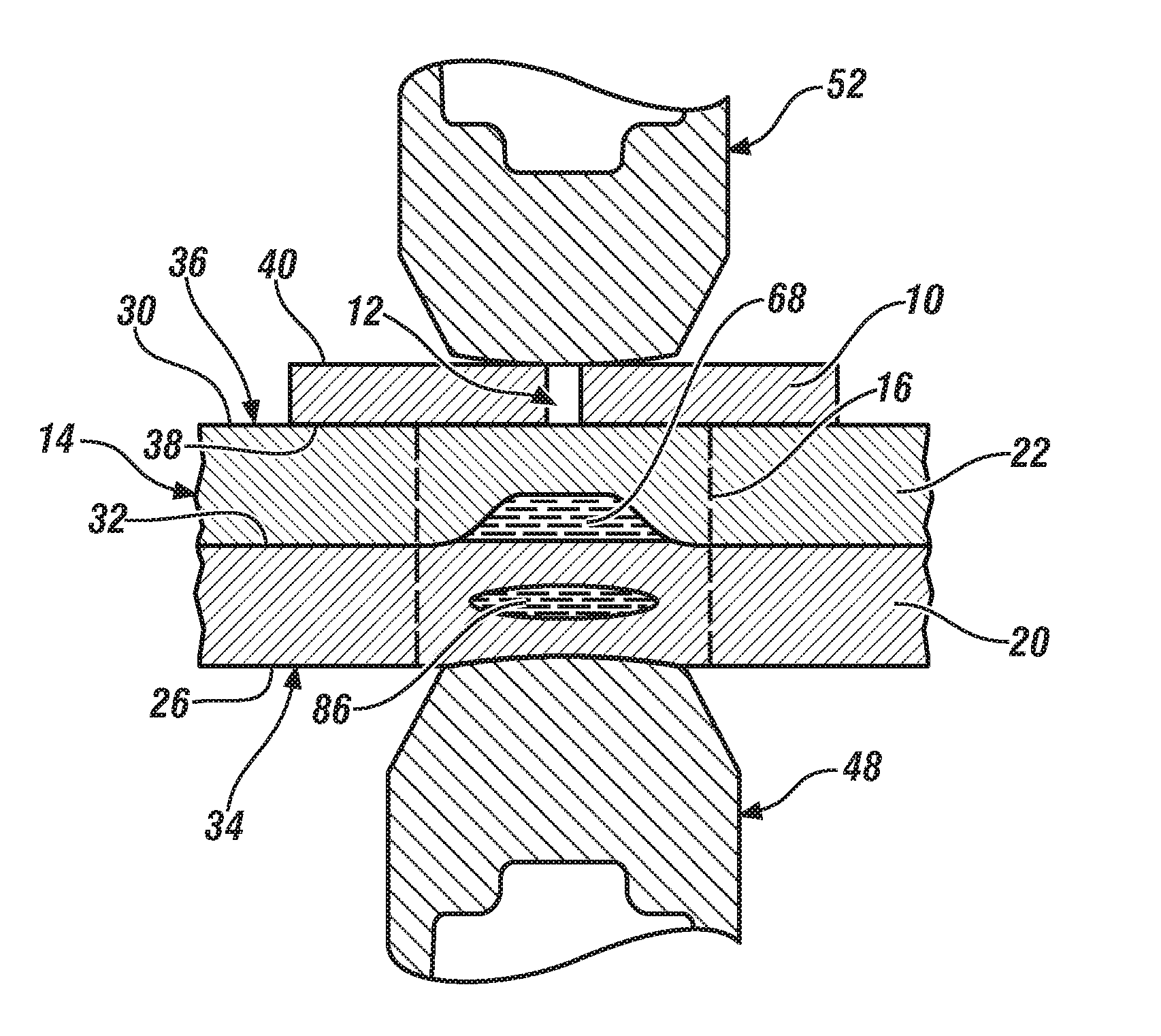
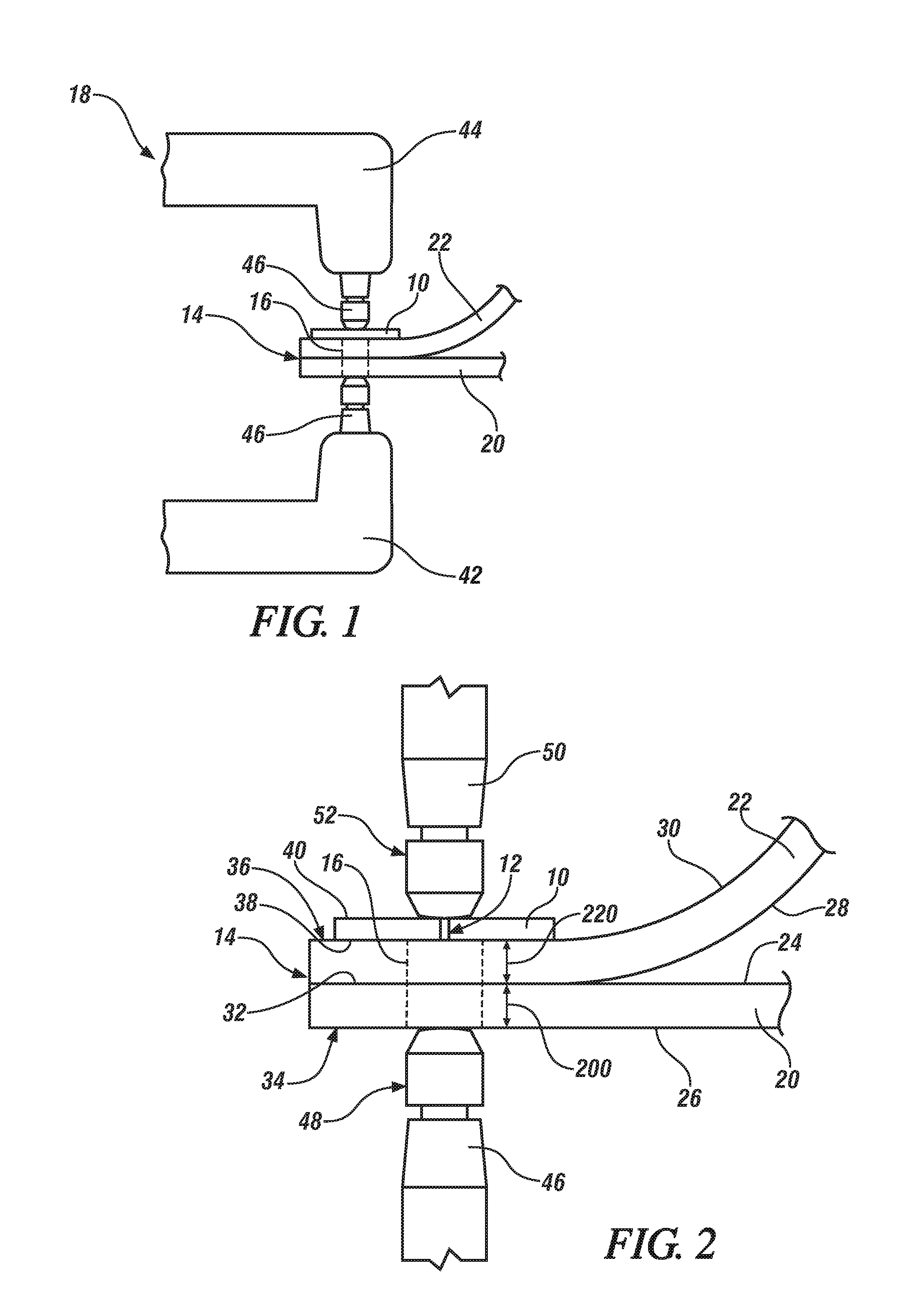
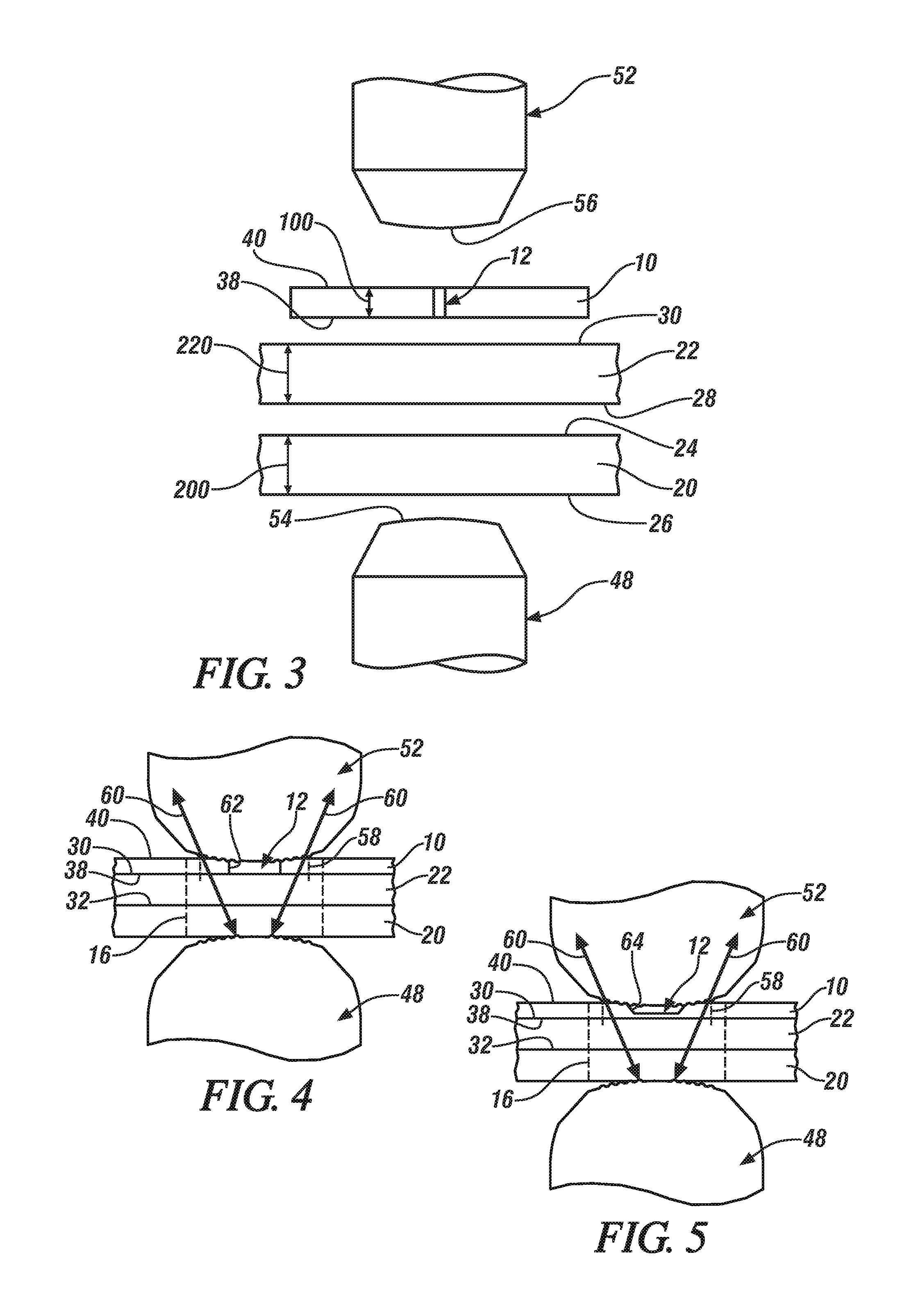
[0028]Preferred and exemplary embodiments of a method of spot welding a workpiece stack-up that includes a steel workpiece and an adjacent aluminum alloy workpiece are shown in FIGS. 1-15 and described below. The described embodiments use a cover plate 10 that includes an intruding feature 12. The cover plate 10 is located adjacent to an aluminum alloy workpiece on one side of the workpiece stack-up between a welding electrode and the workpiece stack-up so as to affect the flow pattern and density of the electrical current that passes through the several overlapping workpieces. Additionally, in some instances, the cover plate 10 provides a medium on the side of the workpiece-stack up between and the aluminum alloy workpiece that lies adjacent to the steel workpiece and the welding electrode that confronts that particular side of the stack-up. In this way, the cover plate 10 can generate heat during current flow and retain heat for a longer duration than the aluminum alloy workpiece ...


PUM

PropertyMeasurementUnit
Fractionaaaaaaaaaa
Fractionaaaaaaaaaa
Thicknessaaaaaaaaaa

Abstract

A method of spot welding a workpiece stack-up that includes a steel workpiece and an adjacent aluminum alloy workpiece involves passing an electrical current through the workpieces and between opposed welding electrodes. The formation of a weld joint between the adjacent steel and aluminum alloy workpieces is aided by a cover plate that is located between the aluminum alloy workpiece that lies adjacent to the steel workpiece and the welding electrode disposed on the same side of the workpiece stack-up. The cover plate, which includes an intruding feature, affects the flow pattern and density of the electrical current that passes through the adjacent steel and aluminum alloy workpieces in a way that helps improve the strength of the weld joint.

Description

CROSS-REFERENCE TO RELATED APPLICATION[0001]This application claims the benefit of U.S. Provisional Application No. 62 / 010,204, filed on Jun. 10, 2014, the entire contents of which are hereby incorporated by reference.TECHNICAL FIELD[0002]The technical field of this disclosure relates generally to resistance spot welding and, more particularly, to resistance spot welding a steel workpiece and an aluminum alloy workpiece.BACKGROUND[0003]Resistance spot welding is a process used by a number of industries to join together two or more metal workpieces. The automotive industry, for example, often uses resistance spot welding to join together pre-fabricated metal workpieces during the manufacture of a vehicle door, hood, trunk lid, or lift gate, among others. A number of spot welds are typically formed along a peripheral edge of the metal workpieces or some other bonding region to ensure the part is structurally sound. While spot welding has typically been practiced to join together certa...

Claims


Application Information

Patent Timeline
IPC IPC(8): B23K11/36B23K11/20B23K11/11
CPCB23K11/36B23K11/20B23K11/115B23K2103/20
Inventor SIGLER, DAVID R.CARLSON, BLAIR E.YANG, DAVIDWANG, HUI-PING
Owner GM GLOBAL TECH OPERATIONS LLC
Features
  • R&D
  • Intellectual Property
  • Life Sciences
  • Materials
  • Tech Scout
  • Unparalleled Data Quality
  • Higher Quality Content
  • 60% Fewer Hallucinations
Learn More