
Laser system and method for operating the laser system

a laser system and laser technology, applied in boring tools, dental tools, radiation therapy, etc., can solve the problems of deceleration of tissue regeneration and attachment, reduced inflammatory response, and inability to effectively clean and decontaminate all intra-radicular space, so as to reduce the damage of laser damage to tooth pulp, minimize the effect of reducing the damage, and reducing the damage of laser damage to the tooth pulp

Active Publication Date: 2015-08-13
FOTONA D O O
View PDF3 Cites 10 Cited by
  • Summary
  • Abstract
  • Description
  • Claims
  • Application Information

AI Technical Summary

Benefits of technology

[0013]The present invention utilizes an improved scientific understanding of the interaction of pulsed laser light with a highly absorbing liquid. Namely, when a pulsed laser beam which is highly absorbed in liquids is delivered to such a liquid, a bubble oscillation sequence develops with a very high oscillation frequency in the range from about 1 kHz to about 10 kHz. By delivering laser energy to a liquid in temporally limited pulse sets containing up to twenty individual laser pulses, and adjusting the pulse repetition rate of the pulses to match the bubble oscillation dynamics, firstly an improved light-to-acoustic energy conversion is obtained, and secondly an extended duration of acoustic transients for better disinfection can be achieved. Moreover, according to a preferred embodiment of the invention, laser pulses may be delivered and synchronized with the bubble oscillation dynamics in such a manner that elongate bubbles with a channel like shape are formed, extending the length of the vapor bubble deeper into the liquid along the direction of the laser beam. Bubbles extending deeper into the liquid filled cavity are desirable, for example, when treating deep cavities. Additionally, when laser energy with a strongly absorbed wavelength is delivered to a liquid in a non-contact manner, creating extended, channel shaped bubbles is advantageous since it moves at least partially the bubble's energy away from the liquid surface, effectively reducing the undesirable influence of the liquid surface on the LA efficiency. However, it also can be expedient to form bubbles with a generally spherical shape, if the conditions require.
[0022]More generally, various shortcomings of prior medical devices and methods (for example, endodontic treatments) can be addressed by utilizing a medical and dental treatment system or other exemplary system configured in accordance with principles of the present disclosure. For example, a more efficacious disinfection of the treated anatomical cavities can be achieved. Additionally, laser ablation of the root canal may be reduced, minimized, and / or eliminated. Moreover, laser damage to tooth pulp may be reduced, minimized, and / or eliminated. Additionally, thermal damage arising from localized heating of a treatment liquid may be reduced, minimized, and / or eliminated. Also, a system configured in accordance with principles of the present disclosure requires lower output characteristics, and is therefore smaller and less costly to produce. Wavelengths (such as, for example, a Ho:YAG at 2.1 μm, or an Nd:YAP at 1.34 μm), otherwise less suitable for the treatment due to their lower absorption in liquid may be used as well. Moreover, in certain embodiments no fiber tip is required to be immersed into the liquid. Yet further, when utilized in connection with mechanical treatment of bone, residual smear layers of loose bone material may be cleared from the inner surface of a drilled hole.

Problems solved by technology

The complexity of the root canal system is well known.
The effectiveness of debriding, cleaning and decontaminating effectively all the intra-radicular space is often limited, given the anatomical complexity and given the inability of common irrigants to penetrate into the lateral canals and / or the apical ramifications.
A debriding, cleaning and decontaminating effectively of the root system thus represents a challenge.
This may lead to increased inflammatory response and decelerated tissue regeneration and attachment.
Early attempts at laser use in endodontics typically resulted in occlusion of dentinal tubules, thereby undesirably decreasing their permeability.
These approaches permit fluid interchange and the removal of organic tissue and microbes, resulting in tubular dentin disinfection.
There is therefore no substantial interaction between the acoustic transients caused by individual pulses, resulting in a limited laser light-to-acoustic (LA) energy conversion efficiency.
Even more importantly, in this prior art method, the bacteria within the treated anatomical cavity are submitted to acoustic transients of a relatively short duration.
When subjected to acoustic transients, the bacteria's structure is disrupted and the bacteria die, providing that the exposure to the transients is extensive enough to be fatal.
There are at least two shortcomings of this approach: i) Special tip is required to perform the treatment, which adds to the complexity and cost of the treatment.
Moreover, the fiber tip is susceptible to damage since it can get at least partially shattered under the strong acoustic transients within the liquid.
Undesirable fragmented fiber particles may therefore remain within the cavity after the treatment.
This makes the prior art method less safe, and also less effective since the strength of the acoustic transients must be adjusted to be below the damage threshold of the fiber tip; ii) The angular distribution of a laser beam coming out of an elongate fiber is broad and omnidirectional with a lack of collimation, which results in insufficient laser energy conversion.

Method used


Image

  • Laser system and method for operating the laser system
  • Laser system and method for operating the laser system
  • Laser system and method for operating the laser system

Examples


Embodiment Construction

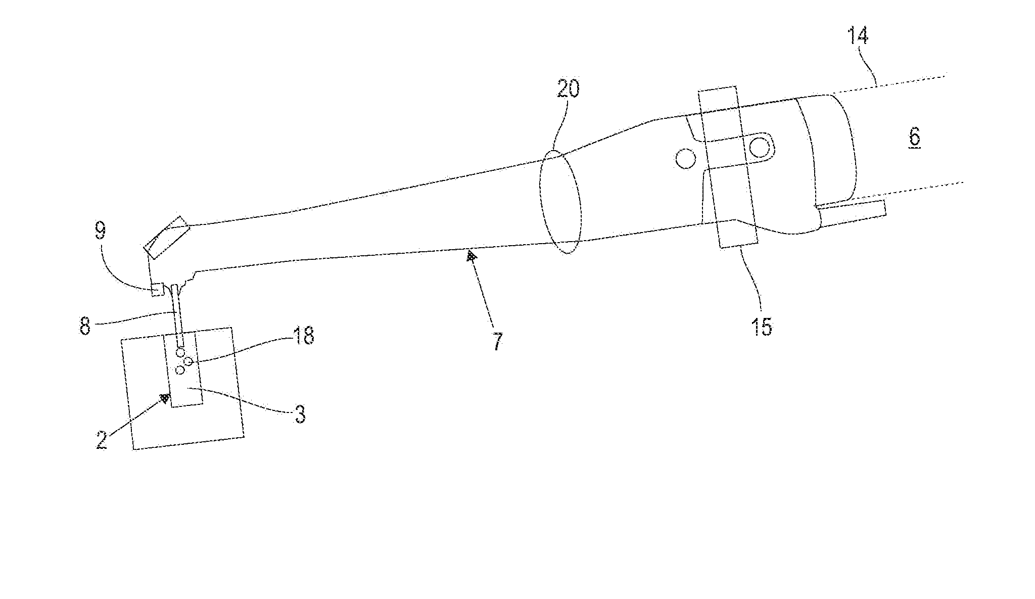
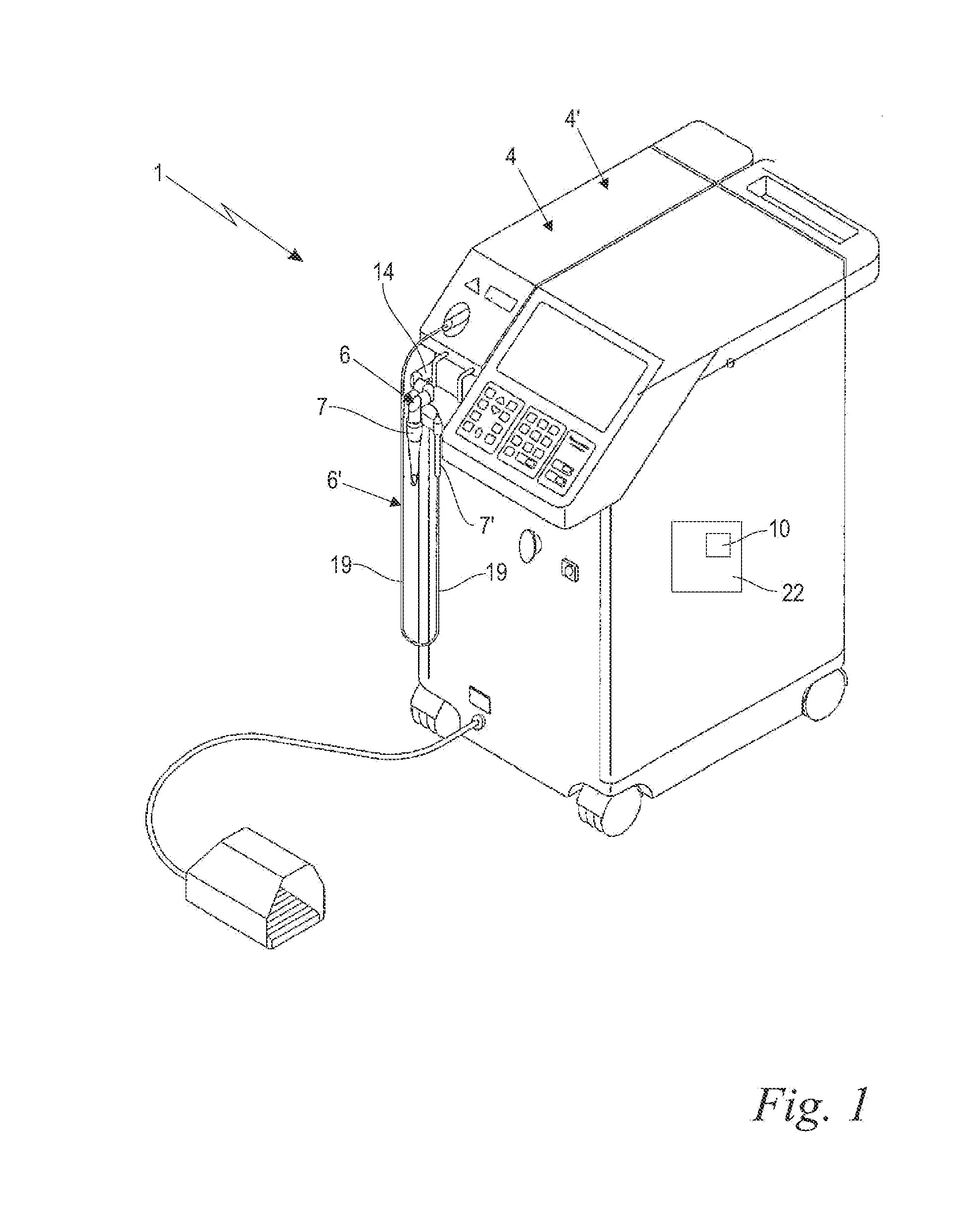
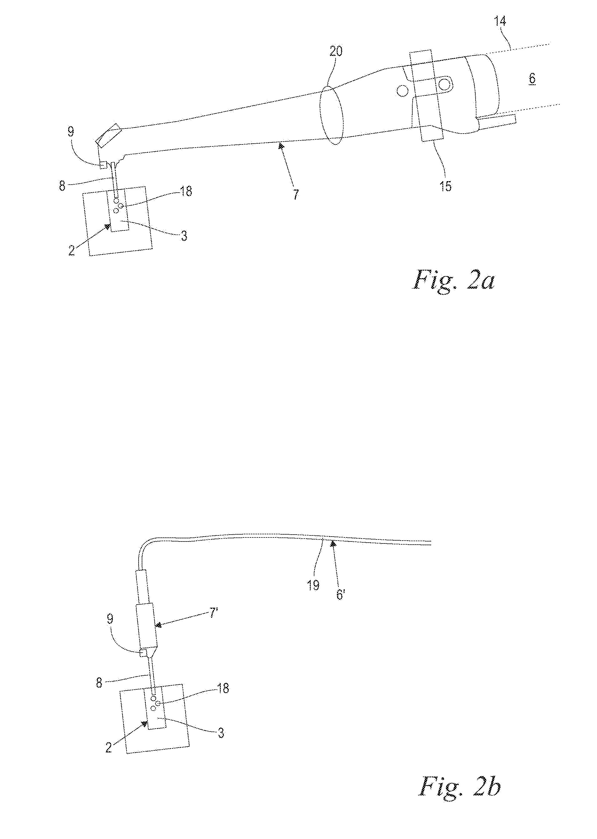
[0043]With reference now to FIG. 1, in various embodiments, a medical treatment laser system 1 comprises at least one laser source 4 for generating a laser beam 5 (FIGS. 4a to 6b), and an optical delivery system 6 for the laser beam 5. The laser system further comprises a schematically indicated control unit 22 for controlling the laser beam 5 parameters, wherein the control unit 22 includes again schematically indicated adjusting means 10 for adjusting the laser beam 5 parameters as described below. The optical delivery system 6 preferably includes an articulated arm 14 and a treatment handpiece 7, wherein the laser beam 5 is transmitted, relayed, delivered, and / or guided from the laser source 4 through the articulated arm 14 and the handpiece 7 to a target. The articulated arm 14 might preferably be an OPTOFLEX® brand articulated arm available from Fotona, d.d. (Slovenia). In the shown preferred embodiment a second laser source 4′ and a second optical delivery system 6′ with a sec...


PUM


Abstract

A dental irrigation system is provided with a laser source for generating a laser beam and an optical delivery system for the laser beam. The laser beam wavelength ranges from 0.4 μm to 11.0 μm. The laser system operates in pulsed operation with pulse sets of 2 to 20 individual pulses of temporally limited pulse length. The pulse sets follow one another with temporal separation. The individual pulses follow one another with pulse repetition rate. The laser system generates at least one vapor bubble within the liquid irradiated with the laser beam. A single pulse causes the vapor bubble to oscillate between a maximal and a minimal volume with a bubble oscillation frequency. The pulse repetition rate within one pulse set is adjusted relative to the bubble oscillation frequency such that synchronization between delivery of the pulses and bubble oscillation is achieved.

Description

BACKGROUND OF THE INVENTION[0001]The present invention relates to a laser system for irrigation, including debriding, cleaning and decontamination, of anatomical cavities filled with a liquid.[0002]There are many medical treatments, such as in endodontics, periodontics, implantology, or bone surgery where an effective irrigation, including debriding, cleaning and decontamination of the anatomical cavities is desirable.[0003]For example, a goal of endodontic treatment is typically to obtain an effective cleaning and decontamination of the root canal system (e.g., removal of bacteria and other contaminants from the smear layer). Clinically, traditional endodontic techniques use mechanical instruments as well as ultrasound and chemical irrigation, in an attempt to shape, clean and completely decontaminate the endodontic system.[0004]The complexity of the root canal system is well known. Numerous lateral canals (with various dimensions and with multiple morphologies) branch off from the...

Claims


Application Information

Patent Timeline
IPC IPC(8): A61C1/00A61N5/06A61C17/02
CPCA61C1/0069A61C1/0046A61N2005/0644A61N5/062A61N2005/067A61C17/0202A61N5/0603A61N5/0624A61B18/201A61B2018/263A61N5/067A61B2017/00172
Inventor LUKAC, MATJAZKAZIC, MARKO
Owner FOTONA D O O
Learn More