
Amorphous ionically-conductive metal oxides, method of preparation, and battery

a metal oxide and ion-conductive technology, applied in the field of forming an amorphous ion-conductive metal oxide, can solve the problems of lithium as an anode material, irreversible battery capacity loss, and diminished performance over time and safety issues

Inactive Publication Date: 2015-06-25
JOHNSON IP HLDG LLC
View PDF5 Cites 68 Cited by
  • Summary
  • Abstract
  • Description
  • Claims
  • Application Information

AI Technical Summary

Benefits of technology

The patent text describes a method for making an amorphous ionically conductive metal oxide with specific formulas and a solid state battery using this material. The method involves introducing a precursor mixture of gases and materials into a reactor chamber and depositing the metal oxide onto a substrate. The resulting material has good ionic conductivity and can be used as a solid state electrolyte in batteries. The technical effect is the production of a reliable and efficient solid state battery.

Problems solved by technology

However, the use of lithium as an anode material has presented problems because many materials that are otherwise very effective as electrolytes react adversely with lithium.
As another example, many ionically-conductive liquids are effective for ion transport but contribute to diminished performance over time and safety issues.
Its formation causes irreversible battery capacity loss associated with the active lithium consumption during the initial SEI layer formation.
Additional SEI layer growth in subsequent charge-discharge cycles further lowers the battery capacity by irreversible depletion of the active lithium, also limiting the cycle life of the battery.
A limitation of the reported compounds is that they have either high ionic conductivity or high electrochemical stability, but not both.
However, in an attempt to cycle a LiCoO2 / cLLZ / Li cell, the discharge capacity was very low, much lower than expected based on the quantity of LiCoO2 cathode involved, which was mostly attributed to the high interfacial resistance between the cLLZ pellet and electrodes.
This diffusion layer undergoes further changes during electrochemical charge-discharge cycles and severely limits the performance of the solid state battery.
Thus, lowering the deposition temperature can substantially decrease or eliminate the diffusion process and lower the interface resistance.
Since even a single remaining pinhole may result in the failure of a cell, a second continuous layer of solid electrolyte may be applied.
However, such films require expensive vacuum equipment for sputtering and are unstable in air (Nimisha et al., Solid State Ionics 185, 47-51 (2011)), making sample handling and transferring during manufacturing very complicated and expensive.

Method used


Image

  • Amorphous ionically-conductive metal oxides, method of preparation, and battery
  • Amorphous ionically-conductive metal oxides, method of preparation, and battery
  • Amorphous ionically-conductive metal oxides, method of preparation, and battery

Examples


example 1

Preparation and Analysis of LLZO Film Using APCVD

LLZO Film Preparation

[0057]A precursor solution for LLZO was prepared by dissolving at room temperature 0.5 grams of lithium acetylacetonate, 0.58 grams of lanthanum nitrate La(No3)3xH2O and 0.33 grams of zirconium acetylacetonate in 240 mL of ethanol, commercially available from Strem Chemicals and Sigma Aldrich. The amount of metal precursors corresponds to a molar ratio of lithium to lanthanum to zirconium of 7:2:1. An ultrasonic nebulizer was used to generate an aerosol mist of the precursor solution and a carrier gas (nitrogen) transported the aerosol mist to the substrate. In the aerosol, the liquid droplet size distribution was in the range of 5-20 μm, leading to easy evaporation of the droplets before they reached the substrate surface. A reactant gas (oxygen) was introduced to the deposition chamber separate from the mist. Glass substrates, aluminum foil, and cathodes were used as substrates, which were heated to about 270 to...

example 2

Preparation and Analysis of Amorphous LLZO by APCVD with Partial Substitution by Tantalum

[0065]An amorphous LLZO film with partial tantalum substitution was prepared by mixing 0.53 grams of lithium acetylacetonate (LiAcac), 0.62 grams of hydrated lanthanum nitrate La(NO3)3xH2O (LaNO), 0.28 grams of zirconium acetylacetonate (ZrAcac) and 0.08 grams of tantalum n-butoxide in 240 ml of ethanol solvent to form a precursor solution. All solution components are commercially available from Strem Chemicals, Sigma Aldrich, and Gelest. An ultrasonic nebulizer was used to generate an aerosol mist of the precursor solution and a carrier gas (nitrogen) was used to transport the mist into the deposition chamber and onto the substrate (glass with sputtered Al bars). A reactant gas (oxygen) was introduced to the deposition chamber separately from the mist. The substrate was heated to about 320° C., facilitating decomposition of the precursors and film deposition on the hot substrate. The deposition...

example 3

Preparation and Analysis of Amorphous LLZO by APCVD with Partial Substitution by Niobium

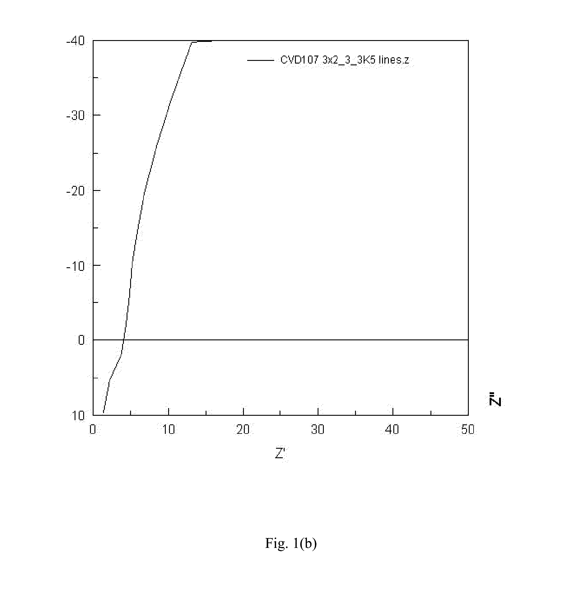
[0067]A sample of amorphous LLZO with partial substitution by niobium was prepared as described in Example 2, with the exception of the precursor solution. The metal precursor solution contained 0.53 grams of LiAcac, 0.62 grams of LaNO, 0.27 grams of ZrAcac and 0.07 grams of niobium n-butoxide in 240 mL of ethanol. All solution components are commercially available from Strem Chemicals, Sigma Aldrich, and Gelest. The Nyquist plot was similar to the Nyquist plot for Example 2, indicating pure ionic conduction and leading to an ionic conductivity estimate of 6.8E-4 S / cm.


PUM

PropertyMeasurementUnit
temperatureaaaaaaaaaa
ionic conductivityaaaaaaaaaa

Abstract

A method for forming an amorphous ionically conductive metal oxide, such as lithium lanthanum zirconium oxide (LLZO), by chemical vapor deposition (CVD), as well as to the ionically conductive material formed by the method, are provided. Such a material may be utilized as a solid electrolyte and / or as a solid separator in an all solid state lithium battery.

Description

CROSS-REFERENCE TO RELATED APPLICATIONS[0001]This application is a Section 371 application of International Application No. PCT / US2012 / 027545 filed Mar. 2, 2012, which was published on Jun. 13, 2013 under International Publication No. WO 2013 / 085557 and which claims priority to U.S. provisional application No. 61 / 566,908, filed Dec. 5, 2011, the entirety of which are herein incorporated by reference.BACKGROUND OF THE INVENTION[0002]This invention relates to a method for forming an amorphous ionically conductive metal oxide, such as lithium lanthanum zirconium oxide (LLZO), by chemical vapor deposition (CVD), as well as to the ionically conductive material formed by the method. Such a material may be utilized as a solid electrolyte and / or a solid separator in an all solid state, or ceramic, battery cell.[0003]A battery cell is a particularly useful article that provides stored electrical energy that can be used to energize a multitude of devices, particularly portable devices that re...

Claims


Application Information

Patent Timeline
Patent Type & Authority Applications(United States)
IPC IPC(8): H01M2/16H01M10/0562H01M10/0525C23C16/40H01M50/449
CPCH01M2/1686C23C16/409H01M2220/30H01M10/0525H01M2300/0071H01M10/0562C01G25/006C23C16/40H01B1/08H01M10/052H01M2300/0094C01P2004/03C01P2006/40Y02E60/10H01M50/449
Inventor JOHNSON, LONNIE G.BABIC, DAVORINKRUMENAKER, ELENA N.CAMPBELL, TEDRIC D.CLAFFEY, KIERAN J.
Owner JOHNSON IP HLDG LLC
Learn More