
ESD protection device and method for manufacturing the same

Active Publication Date: 2015-06-18
MURATA MFG CO LTD
View PDF7 Cites 6 Cited by
  • Summary
  • Abstract
  • Description
  • Claims
  • Application Information

AI Technical Summary

Benefits of technology

The present invention provides an ESD protection device that is reliable and efficient in insulation, with excellent discharge characteristics. Additionally, a manufacturing method for the ESD protection device is also provided.

Problems solved by technology

However, the electrostatic countermeasure component disclosed in Patent Document 1 has a problem in that the discharge starting voltage and the peak voltage cannot be easily decreased.
In addition, when static electricity is repeatedly applied, degradation in characteristics, such as increase in discharge starting voltage and peak voltage, may also disadvantageously occur.
That is, there has been a problem in that the discharge starting voltage and the peak voltage cannot be easily controlled.
The reason for this is that since the thickness of the passive layer formed on the surface of each metal grain contained in the electrostatic protection material layer is relatively small, when static electricity is repeatedly applied thereto, the passive layer is liable to be fractured, and as a result, a short circuit defect occurs.

Method used


Image

  • ESD protection device and method for manufacturing the same
  • ESD protection device and method for manufacturing the same
  • ESD protection device and method for manufacturing the same

Examples


experimental examples

Formation of Evaluation Sample

[0089](1) Formation of Metal Grains

[0090]As an alloy powder before heat treatment, alloy powders S-1 to S-5 shown in Table 1 were prepared. Those alloy powders were each formed by an atomizing method. The “Grain Distribution” shown in Table 1 was determined by a laser diffraction grain distribution method. In addition, the “Composition” shown in Table 1 was determined by an ICP-AES method (inductively-coupled plasma atomic emission spectrometry).

TABLE 1AlloyCompositionGrainPowder(Percent by Mole)Distribution (μm)SymbolType of MetalCuAlD10D50D90S-1Cu—Al-Based Alloy9551.22.55.4S-2Cu—Al-Based Alloy80201.22.55.4S-3Cu—Al-Based Alloy60401.22.55.1S-4Cu—Al-Based Alloy90100.81.32.6S-5Cu—Al-Based Alloy50500.81.32.6

[0091]Next, a heat treatment was performed on each of the alloy powders S-1 to S-5 shown in Table 1 in accordance with the heating profile shown in FIG. 4 to provide metal powders M-1 to M-9 shown in Table 2. In the column of the “Alloy Powder” in Table...


PUM


Abstract

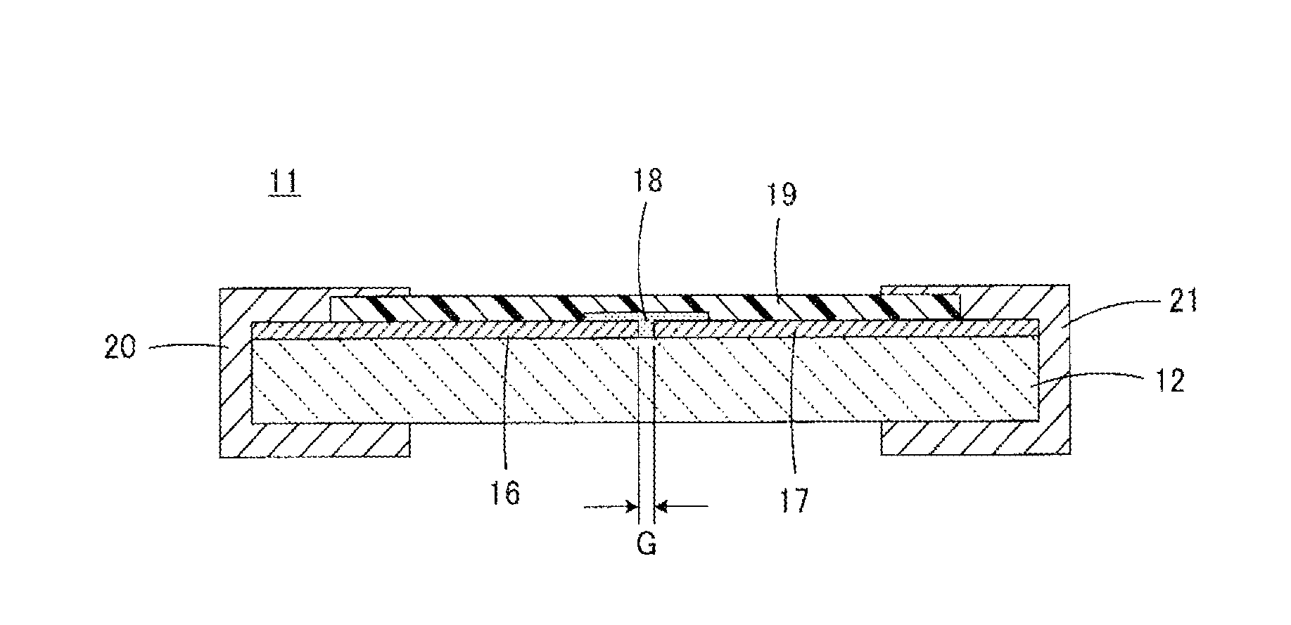
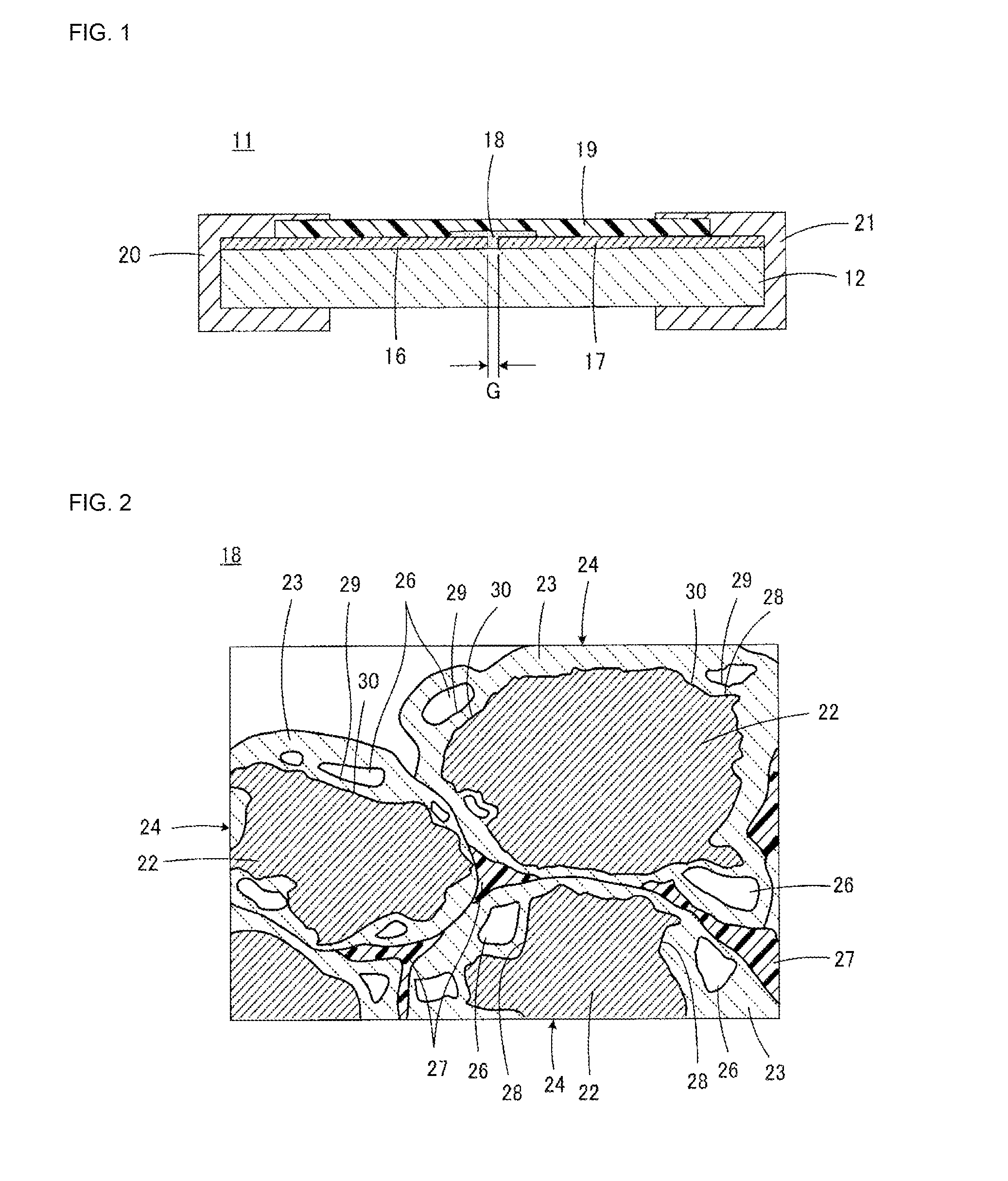
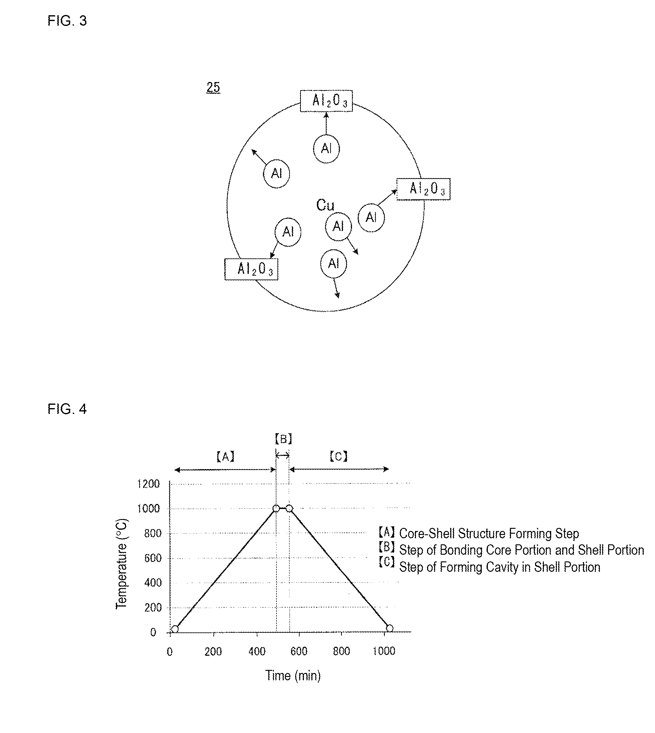
An ESD protection device having high insulation reliability and excellent discharge characteristics is provided. In an ESD protection device including a first and a second discharge electrode disposed to face each other, a discharge auxiliary electrode (18) formed so as to bridge the first and second discharge electrodes, and an insulating substrate holding the first and second discharge electrodes and the discharge auxiliary electrode (18), the discharge auxiliary electrode (18) is formed of an aggregate of metal grains (24) each having a core-shell structure comprising a core portion (22) primarily formed of a first metal and a shell portion (23) primarily formed of a metal oxide containing a second metal, and the aggregate of metal grains (24) further includes an insulating resin (27) which bonds the metal grains (24) to each other.

Description

BACKGROUND OF THE INVENTION[0001]1. Field of the Invention[0002]The present invention relates to an ESD (Electrostatic Discharge) protection device and a method for manufacturing the same, and in particular, relates to improvement of a discharge auxiliary electrode provided to promote an electrostatic discharge in an ESD protection device.[0003]2. Description of the Related Art[0004]The techniques of interest to the present invention include, for example, those described in Japanese Unexamined Patent Application Publication No. 2007-265713 (Patent Document 1).[0005]Patent Document 1 describes an electrostatic countermeasure component which includes at least two lead electrodes provided on a ceramic substrate to face each other and an electrostatic protection material layer provided so as to cover the parts of those lead electrodes and an area located therebetween, and the electrostatic protection material layer is formed from an electrostatic protection material paste which contains...

Claims


Application Information

Patent Timeline
IPC IPC(8): H02H3/20
CPCH02H3/20H01C7/1006H01C7/102H01C7/105
Inventor SUMI, TAKAHIROADACHI, JUNTSUKIZAWA, TAKAYUKIISHIKAWA, KUMIKO
Owner MURATA MFG CO LTD
Learn More