Welding light metal workpieces by reaction metallurgy

a reaction metal and workpiece technology, applied in the direction of soldering apparatus, manufacturing tools, auxillary welding devices, etc., can solve the problems of complex joining of light metals such as aluminum alloys or magnesium alloys, short electrode life, and difficulty in spot welding of both alloy types, so as to minimize the distortion of the weld region, and minimize the effect of unwanted deformation

Active Publication Date: 2015-06-11
GM GLOBAL TECH OPERATIONS LLC
View PDF1 Cites 4 Cited by
  • Summary
  • Abstract
  • Description
  • Claims
  • Application Information

AI Technical Summary

Benefits of technology

The patent describes a process for joining aluminum alloy and magnesium alloy materials together using a reactive material between the sheets. The reactive material is heated and reacts with the workpiece surfaces to form a low-melting point liquid that removes oxides and other chemical barriers to a weld. The process results in a mobile reaction product that is controllable to manage the dimensions of the welded article and minimize distortion of the members at the welded interface. The temperature of the interface is controlled to remain below the solidus temperatures of the workpiece surfaces, and care is taken to minimize unwanted deformation of the cleaned, but heated, welding faces. The process is useful for welding workpieces together over substantial surface areas and can also join aluminum-coated or zinc-coated steel members to light metal workpieces.

Problems solved by technology

Joining light metals such as aluminum alloys or magnesium alloys is complicated by the presence of rapidly forming oxide layers as well as their inherent high electrical and thermal conductivity.
Spot welding of both of these alloy types is typically difficult and requires preparation of the workpiece surface, high currents, high forces, and mechanically well-aligned and stable electrodes.
Short electrode lives are common because of reaction between the workpiece alloy and copper electrode.
The resultant weld can have high strength, but poor high cycle fatigue performance under some conditions, particularly for magnesium alloys.
For riveting, a large inventory of expensive rivets is needed to join the various gauge combinations encountered in a structure.

Method used


Image

  • Welding light metal workpieces by reaction metallurgy
  • Welding light metal workpieces by reaction metallurgy
  • Welding light metal workpieces by reaction metallurgy

Examples


Embodiment Construction

[0027]In many embodiments of this invention the process may be used to form solid-state welded interfaces between aluminum alloy workpieces or between magnesium alloy workpieces. Examples of aluminum-base alloys are AA5083 (solidus temperature of 574° C.), AA5454 (solidus 602° C.), and AA6061 (solidus 582° C.). Examples of magnesium-base alloys are AZ31 (solidus temperature of 605° C.), AM60 (solidus temperature of 540° C.), and ZK60 (solidus temperature of 520° C.). In other embodiments of the invention an aluminum-coated steel workpiece or a zinc-coated steel workpiece may be welded to an aluminum alloy or magnesium alloy workpiece.

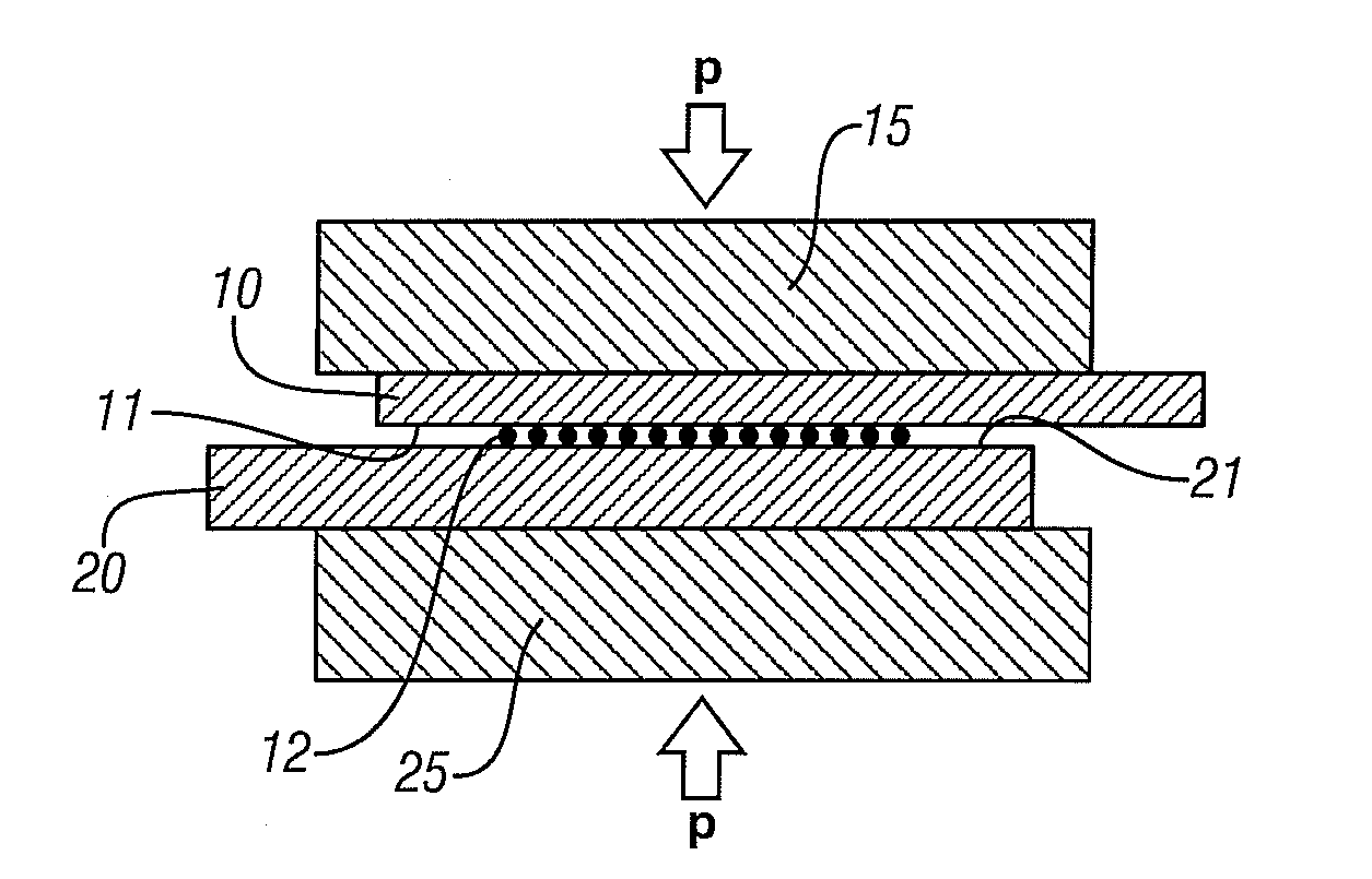
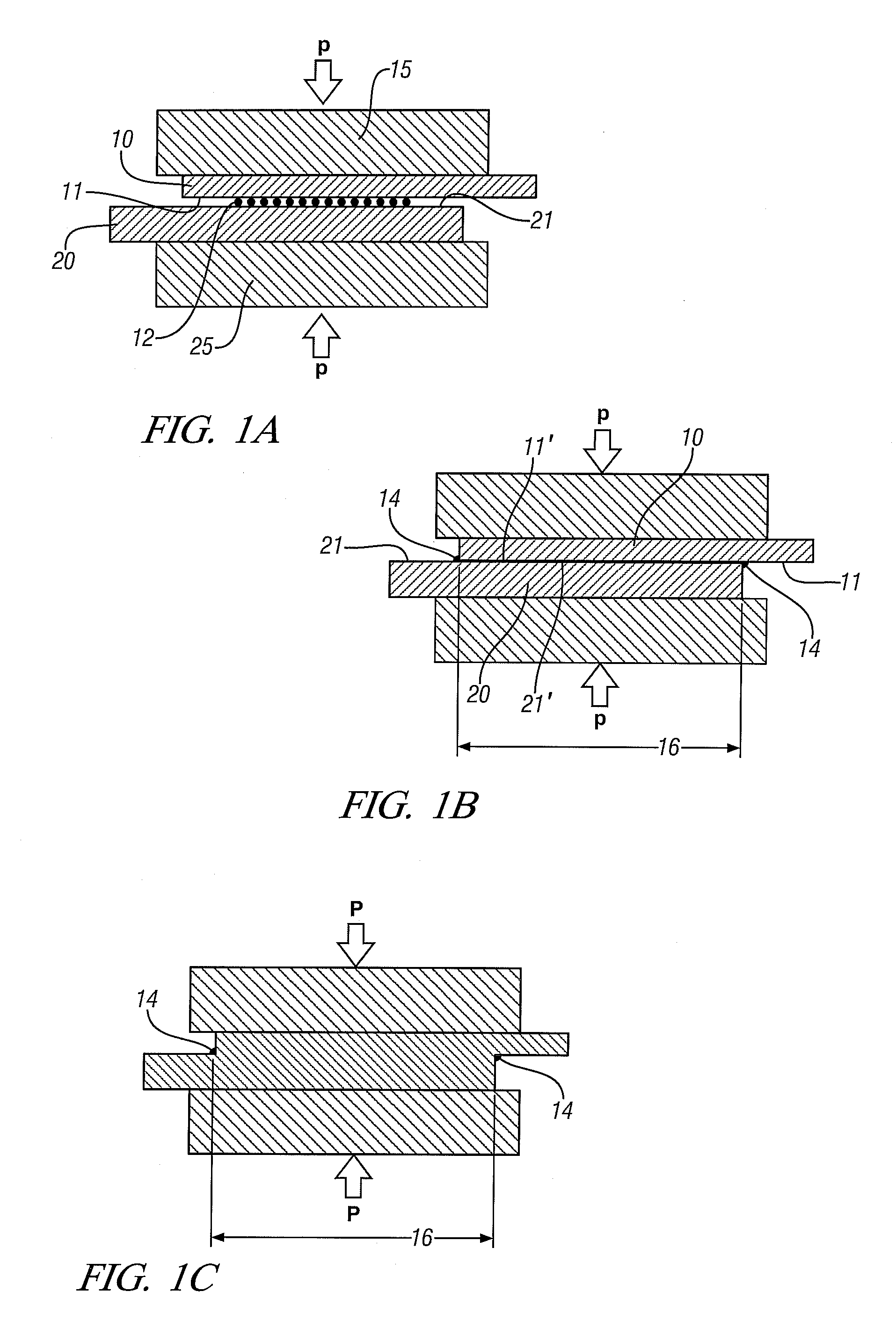
[0028]The process may often be used in welding sheets or other workpieces with relatively thin walls at the joint position. FIGS. 1A-1C are used to illustrate such embodiments.

[0029]In FIG. 1A, two metal workpieces 10 and 20, here shown in an overlapping configuration, are located between two support blocks 15 and 25 respectively with a layer of particu...


PUM

PropertyMeasurementUnit
melting pointaaaaaaaaaa
solidus temperaturesaaaaaaaaaa

Abstract

Aluminum alloy workpieces and / or magnesium alloy workpieces are joined in a solid state weld by use of a reactive material placed, in a suitable form, at the joining surfaces. Joining surfaces of the workpieces are pressed against the interposed reactive material and heated. The reactive material alloys or reacts with the workpiece surfaces consuming some of the surface material in forming a reaction product comprising a low melting liquid that removes oxide films and other surface impediments to a welded bond across the interface. Further pressure is applied to expel the reaction product and to join the workpiece surfaces in a solid state weld bond.

Description

CROSS-REFERENCE TO RELATED APPLICATION[0001]This application is a Continuation of allowed, co-pending, U.S. patent application Ser. No. 12 / 420,927, titled “Welding Light Metal Workpieces by Reaction Metallurgy”, filed on Apr. 9, 2009 and assigned to the assignee of this invention, the contents of which are incorporated herein by reference.TECHNICAL FIELD[0002]This invention relates to solid-state welding processes for joining workpieces of metal alloys such as aluminum alloys or magnesium alloys. A reaction product comprising a mobile low-melting temperature liquid-containing material is temporarily formed between joining surfaces. The mobile material is formed and used to prepare cleaned, oxide-free aluminum or magnesium surfaces. The cleaned surfaces are then pressed together to expel the reaction product and form a metal-to-metal bond without melting the facing surfaces. The process is practiced to manage consumption and deformation of the facing surfaces of the workpieces.BACKGR...

Claims


Application Information

Patent Timeline
Patent Type & Authority Applications(United States)
IPC IPC(8): B23K20/16B23K20/10B23K11/20B23K20/02B23K11/11B23K11/16B23K20/233B23K20/227
CPCB23K20/16B23K20/2333B23K20/10B23K11/20B23K20/023B23K11/11B23K11/163B23K20/2275B23K20/233B23K20/2336B23K2101/18B23K2101/34B23K2103/04B23K2103/08B23K2103/10B23K2103/15B23K2103/18B23K2103/20
Inventor SIGLER, DAVID R.SCHROTH, JAMES G.GAYDEN, XIAOHONG Q.CHEN, YEN-LUNG
Owner GM GLOBAL TECH OPERATIONS LLC
Why Eureka
Try Eureka