
Process for producing carbonitrided part

a carbonitride and carbon dioxide technology, applied in the field of carbon dioxide production, can solve the problems of difficult to obtain hard martensite, small hardening depth, and increasing car energy efficiency requirements, and achieve the effects of high pitting strength, excellent abrasion strength, and weight saving

Inactive Publication Date: 2014-12-18
NIPPON STEEL CORP +1
View PDF0 Cites 0 Cited by
  • Summary
  • Abstract
  • Description
  • Claims
  • Application Information

AI Technical Summary

Benefits of technology

The process results in carbonitrided parts with improved abrasion strength and pitting strength, reducing production costs by minimizing Mo content and optimizing microstructure for enhanced durability.

Problems solved by technology

In recent years, requirements on energy efficiency of a car have been becoming severe more and more.
Regarding the “carbonitriding,” there are “gas carbonitriding” where ammonia gas is mixed in a carburizing atmosphere to undergo carburizing and nitriding at the same time and the like, and nitrogen is thought to have an effect of enhancing a so-called “temper softening strength.” However, nitrogen has an effect of suppressing diffusion of carbon, in addition, since nitriding treatment is conducted at a lower temperature than that of carburizing treatment, there has been a problem that hardening depth becomes small.
Further, nitrogen is an austenite-stabilizing element, and lowers an Ms point in the same way as C, thus, retained austenite tends to be present, and there has also been a problem that it is difficult to obtain hard martensite.

Method used


Image

  • Process for producing carbonitrided part
  • Process for producing carbonitrided part
  • Process for producing carbonitrided part

Examples


example

[0100]Steels 1 to 5 having the chemical compositions shown in Table 2 were melted by using a 50 kg vacuum melting furnace and cast to form ingots.

[0101]The above-described steels 1 to 5 are steels having chemical compositions falling within the range regulated by the present invention; and steel 1 is a steel corresponding to the SCr420 specified in JIS G 4053 (2003). Steels 2 to 4 are steels enriched in Si content, Cr content, Si and Cr contents among elements of the SCr420, respectively. Steel 5 is a steel containing Mo in the SCr420, and it is a steel corresponding to the SCM420 specified in the above-described JIS. Additionally, with regard to all steels, as impurities, the content of Ni was 0.02% and the content of Cu was 0.02%.

TABLE 2Chemical composition(% by mass) Balance: Fe and impuritiesSteelCSiMnPSCrMoNote10.220.250.800.0190.0121.00—(a)20.240.800.860.0160.0151.10—30.240.200.860.0150.0151.80—40.230.800.840.0160.0151.80—50.220.250.830.0150.0151.130.16(b)Note:(a) Steel corres...


PUM

PropertyMeasurementUnit
temperatureaaaaaaaaaa

Abstract

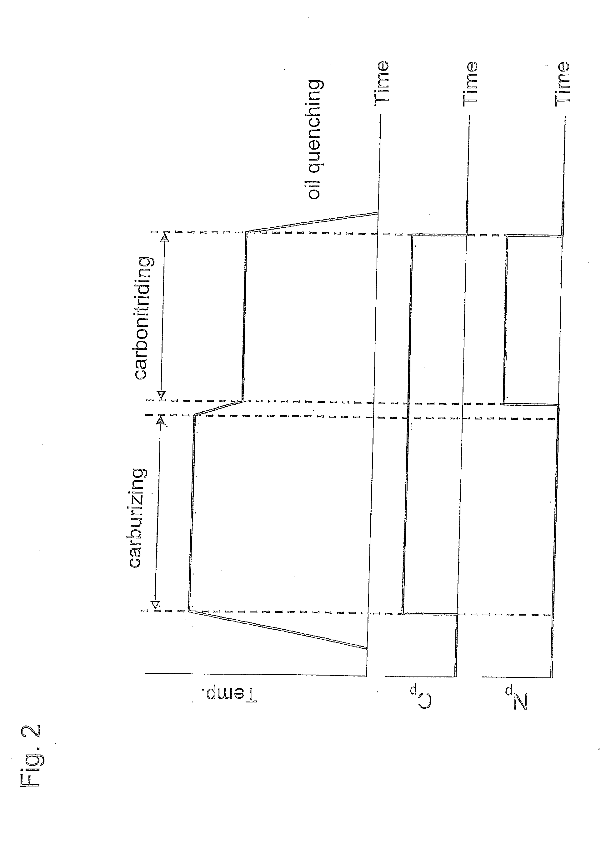
A process for producing a carbonitrided part comprising the steps of preparing a base steel part, having a composition comprising, in mass percent, C: 0.10 to 0.24%, Si: 0.15 to 1.0%, Mn: 0.30 to 1.0%, Cr: 0.40 to 2.0%, S: 0.05% or less, with the balance being Fe and impurities and performing the following steps 1-4 in sequence. Step 1 is carburizing the base steel part under a carburizing atmosphere at a temperature of 900 to 950° C. Step 2 is carbonitriding the base steel part carburized according to step 1 under a carbonitriding atmosphere at a temperature of 800 to 900° C. with a nitrogen potential of 0.2 to 0.6%. Step 3 is quenching the base steel part carbonitrided according to step 2. Step 4 is tempering the base steel part quenched according to step 3 at a temperature of more than 250° C. to not more than 350° C.

Description

[0001]This application is a continuation of the international application PCT / JP2009 / 070152 field on Dec. 1, 2009, the entire content of which is herein incorporated by reference.TECHNICAL FIELD[0002]The present invention relates to a part subjected to carbonitriding treatment (hereinafter referred to as “carbonitrided part”) and a process for producing carbonitrided parts. More specifically, the present invention relates to a carbonitrided part suitable for a power transmission component requiring excellent rolling contact fatigue strength, in particular, a large strength to pitting and excellent abrasion strength, and a process for producing the carbonitrided parts.BACKGROUND ART[0003]Power transmission components such as a gear used for a transmission of a car and a pulley for a belt-type Continuously Variable Transmission (CVT) are conventionally produced as follows: an alloy steel for machine structural use defined in JIS G 4053 (2003) is formed into a predetermined shape by pr...

Claims


Application Information

Patent Timeline
Patent Type & Authority Applications(United States)
IPC IPC(8): C23C8/32C23C8/80
CPCC23C8/32C21D1/18C23C8/80C21D1/06C21D9/32C21D2211/004C21D2221/00C22C38/18C23C8/02C23C8/22C22C38/02C22C38/04C22C38/22
Inventor SANO, NAOYUKIHORIMOTO, MASAYUKIOKADA, YOSHINARIAMANO, MASAKININOMIYA, AKIHITO
Owner NIPPON STEEL CORP
Learn More