


Quick Research
Generate reliable direction feasibility study reports for your R&D in just a few steps.

Technical Q&A
Discover and master advanced knowledge NOW. Basics, ideas, possibilities, all at once.

Find Solutions
As an expert in R&D theories, this can generate solutions to your technical problems instantly.

Evaluate Feasibility
Analyze your overall solution with one click, know your potential R&D risks in advance.

Monitor Landscape
Get weekly tech updates, stay abreast of the latest tech innovations and key insights.
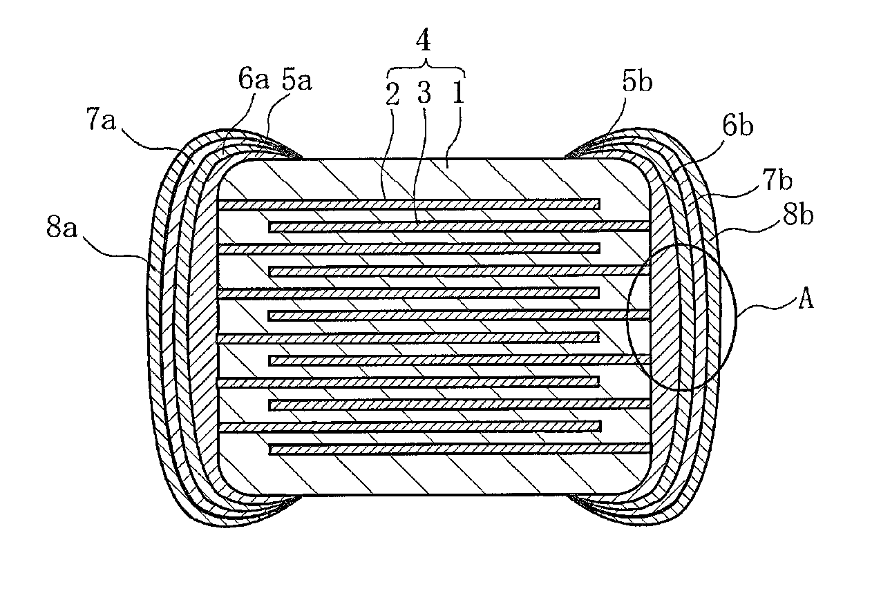
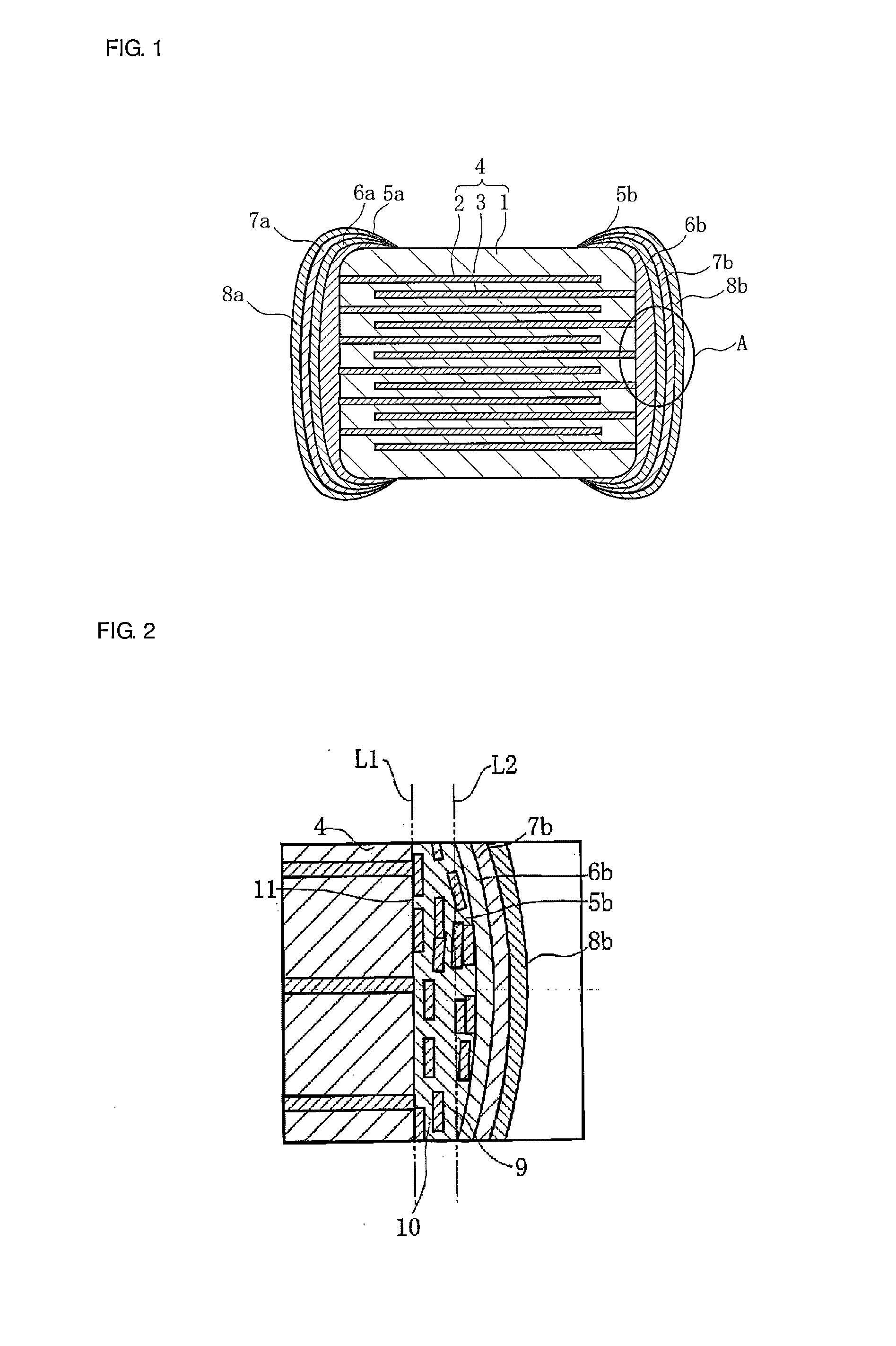
Conductive paste electronic component and method for manufacturing electronic component
a technology of electronic components and conductive paste, which is applied in the direction of fixed capacitor details, capacitors, and conductors, etc., can solve the problems of degradation of resistance and plating solution resistance, inability to effectively avoid humidity resistance degradation, and inability to achieve the effect of improving sealing performance of the surface layer of the external electrode, avoiding corrosion, and improving the adhesion of plating
- Summary
- Abstract
- Description
- Claims
- Application Information
AI Technical Summary
Benefits of technology
Problems solved by technology
Method used
Image

Examples
example 1
[0105]First, H2BO2, SiO2, and A2CO3 (A: Li, Na, or K) were weighed so that a molar content of SiO2 was 6 to 62 percent by mole. In this example, the molar content of SiO2 was obtained by a point analysis using a WDX (wavelength-dispersive x-ray analysis) method after the conductive paste was formed.
[0106]Next, after the materials thus weighed were melted at 1,000° C. to 1,400° C. and were then vitrified by rapid cooling, coarse pulverization and fine pulverization were performed in this order, so that a glass frit having an average particle diameter of 5 μm was formed.
[0107]In addition, an organic vehicle containing 30 percent by weight of an acrylic resin, 40 percent by weight of 3-methoxy-3-methyl-1-butanol, and 30 percent by weight of terpineol was formed.
[0108]Next, after a Cu powder having an aspect ratio a / b of 4.5, the glass frit, and the organic vehicle were mixed with a dispersant so as to obtain a mixture containing 11.5 percent by volume of the Cu powder, ...
example 2
[0130]Test materials (conductive pastes) of Samples Nos. 11 to 17 were formed in such a way that the volume content of a glass frit was set to 5 to 12 percent by volume, the amount of a Cu powder was adjusted in accordance with the decrease or the increase in volume content of the glass frit, and the volume contents of an organic vehicle and a dispersant were set similar to those in Example 1. In this example, the aspect ratio a / b of the Cu powder was 4.5 which was the same as that in Example 1.
[0131]Subsequently, test elements (multilayer ceramic capacitors) of Samples Nos. 11 to 17 were formed by a method and a procedure similar to those in Example 1.
[0132]Next, the humidity / plating solution resistance and the fixing strength of the test element of each of Samples Nos. 11 to 17 were evaluated by a method and a procedure similar to those in Example 1.
[0133]In addition, the cross section of the external electrode in the central region of the end surface of the base component of each...
example 3
[0143]Except that the aspect ratio a / b of the Cu powder was variously changed, test elements of Samples Nos. 21 to 30 were formed by a method and a procedure similar to those in Example 1. In addition, the aspect ratio a / b was measured by a method similar to that in Example 1.
[0144]Next, the cross section of the test element of each of Samples Nos. 21 to 30 was observed using a SEM. In addition, after whether the surface of the external electrode was fully covered with the Cu film or not was checked, a test element in which the external electrode was fully covered with the Cu film was evaluated as good (◯), and a test element in which the external electrode was not fully covered with the Cu film was evaluated as no good (X).
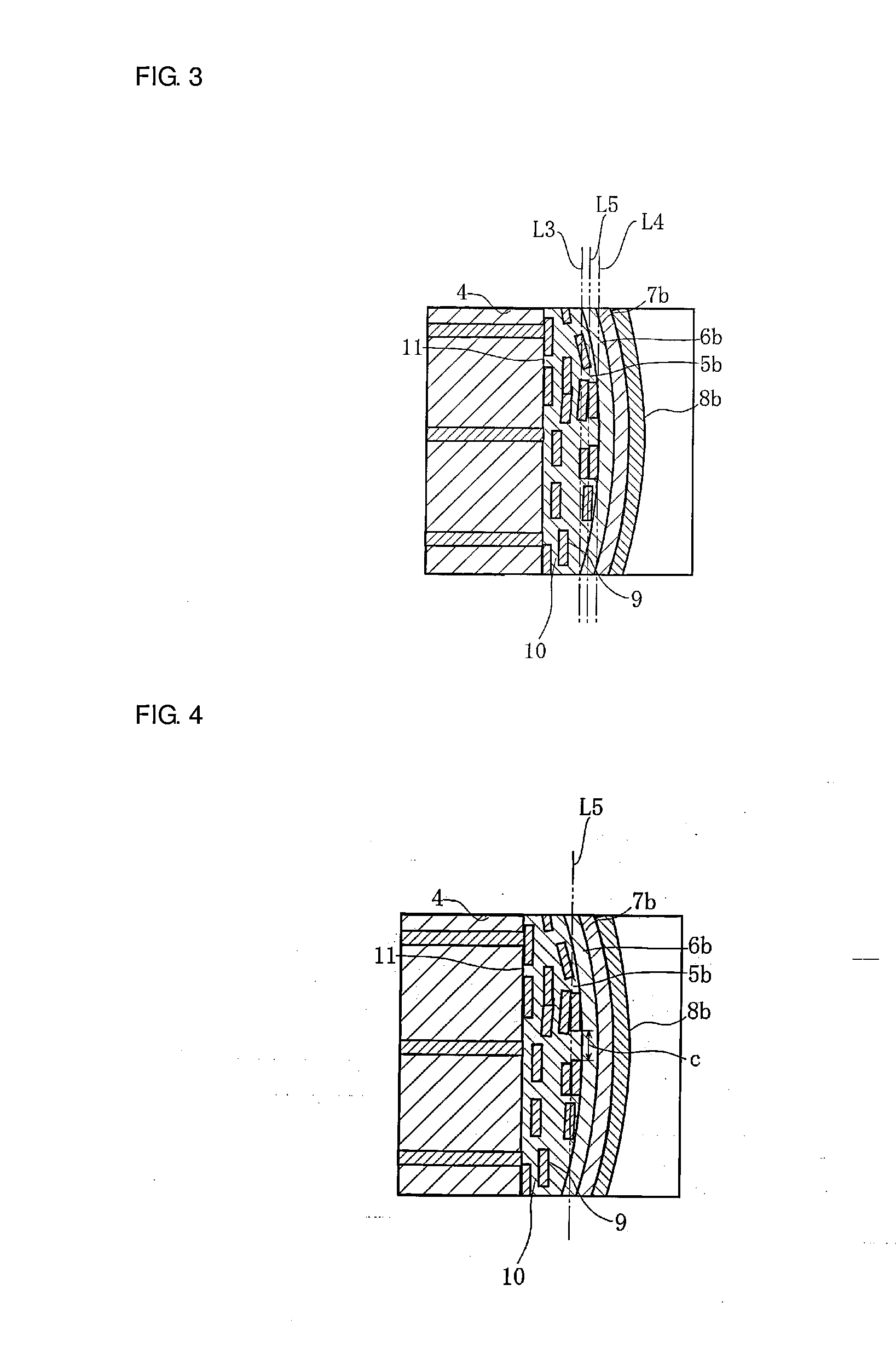
[0145]In addition, the cross section of the external electrode of each test element in the central region of the end surface of the base component was observed using a SEM, and the maximum length c of the glass frit in the external electrode was obtained.
[0146]He...
PUM
| Property | Measurement | Unit |
|---|---|---|
| Temperature | aaaaa | aaaaa |
| Temperature | aaaaa | aaaaa |
| Length | aaaaa | aaaaa |
Abstract
Description
Claims
Application Information
 - R&D Engineer
- R&D Manager
- IP Professional
- Industry Leading Data Capabilities
- Powerful AI technology
- Patent DNA Extraction
Browse by: Latest US Patents, China's latest patents, Technical Efficacy Thesaurus, Application Domain, Technology Topic, Popular Technical Reports.
© 2024 PatSnap. All rights reserved.Legal|Privacy policy|Modern Slavery Act Transparency Statement|Sitemap|About US| Contact US: help@patsnap.com