Electrical apparatus encapsulant
a technology of encapsulant and electrical winding, which is applied in the direction of inhomogeneous insulation materials, transportation and packaging, coatings, etc., can solve the problems of limited thermal stability of encapsulant materials, restricted operating temperature of electrical machines, and chemical and physical compatibility of encapsulant compositions used to mechanically encapsulate electrical windings of high temperature electrical machines. , to achieve the effect of improving the thermal conductivity of encapsulant compositions, increasing the thermal coefficien
- Summary
- Abstract
- Description
- Claims
- Application Information
AI Technical Summary
Benefits of technology
Problems solved by technology
Method used
Image
Examples
example 1
[0053]A first electrical encapsulant composition comprising a silica containing inorganic-organic nano-hybrid matrix, and particles of refractory ceramics suspended in the inorganic-organic nano-hybrid matrix is produced as follows.
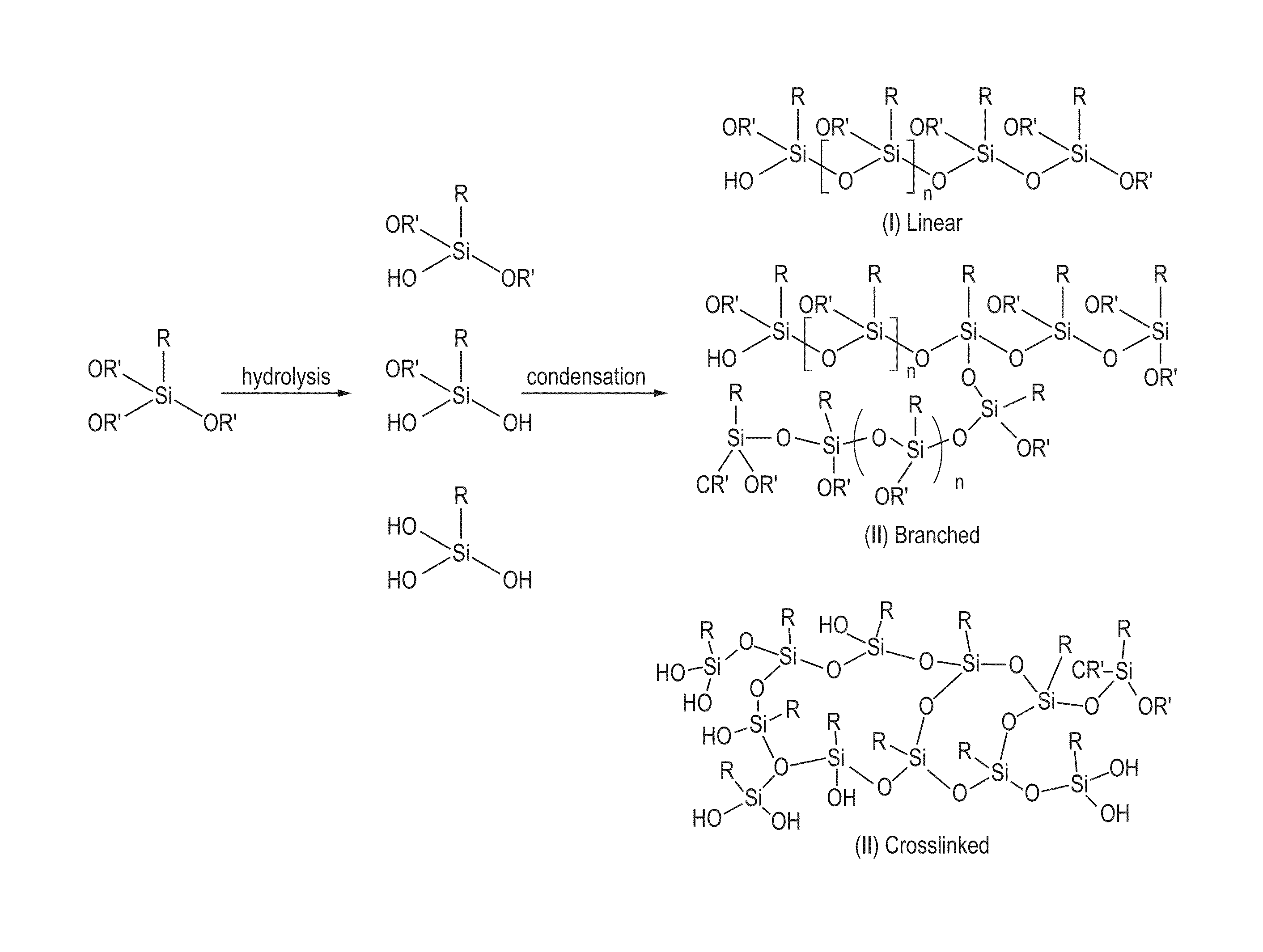
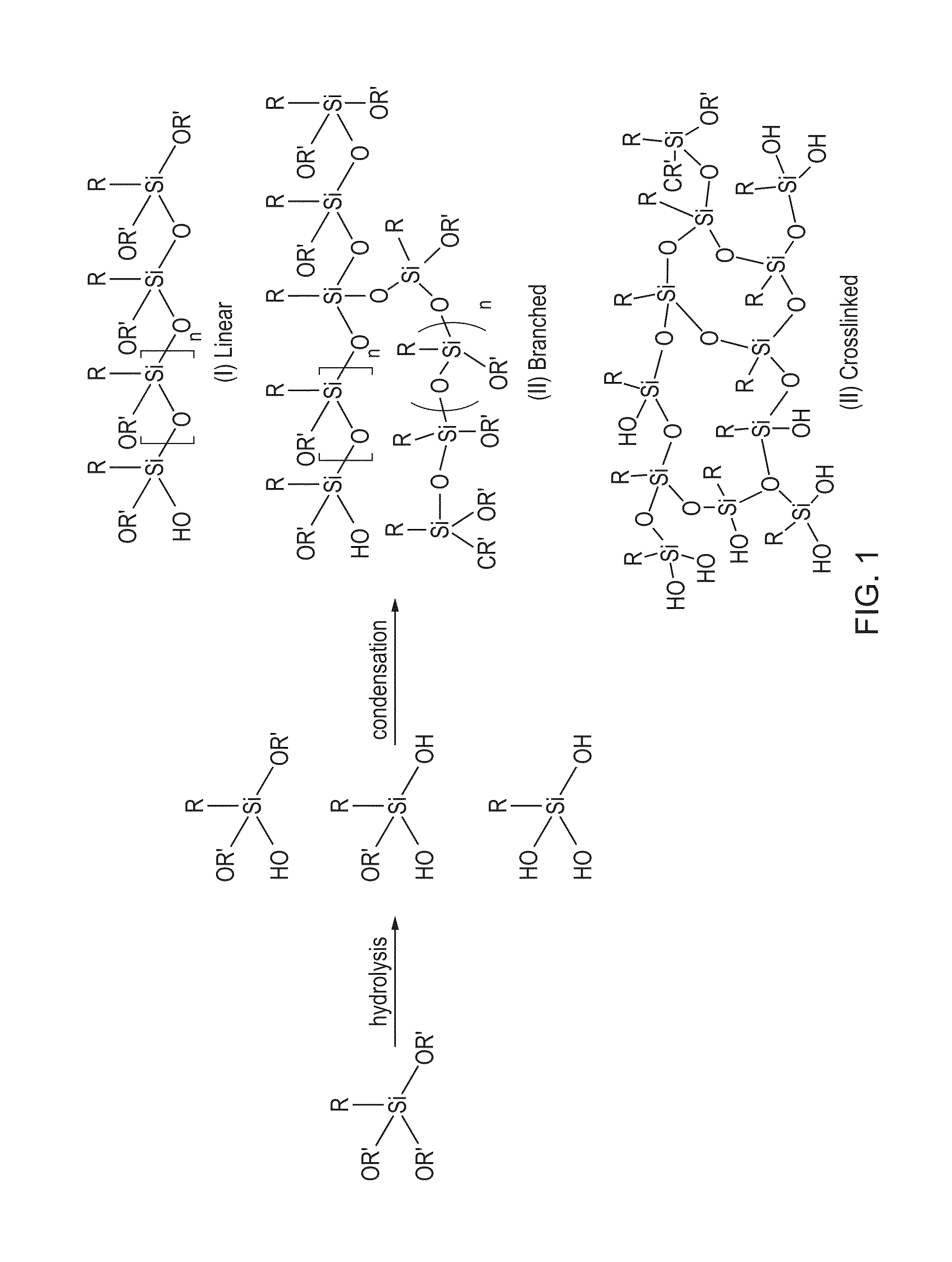
[0054]Silicon containing Methyltrimethoxysilane 40.8 g is charged in a flask. Dilute hydrochloric acid (HCl, 1N concentration) 5.4 g is added drop by drop to this mixture under vigorous stirring. After addition of hydrochloric acid solution, the reaction mixture is heated to reflux for 6 hours and followed by distilling out the by-product, methanol. The nano-hybrid resin thus synthesised is of the structures I and II (see FIG. 1) with a proper fraction of OR′ groups remaining in the molecules because insufficient water is available for hydrolysing all OR′ groups in the example. These OR′ groups have been found to keep the resin in liquid form, and are relatively stable at room temperature. The OR′ groups may be subject to further hydrolysis / condensation w...
example 2
[0057]In example 1, the non-hydrolysable R group is methyl, which remains in the resin after curing. In example 2, a phenyl group is introduced into the nano-hybrid resin.
[0058]A second electrical encapsulant composition can be formed as follows. Methyltrimethoxysilane 32.6 g and phenyltriethoxysilane are mixed in a flask. 5.94 g HCl solution is dropped into the mixture under vigorous stirring. After addition of HCl solution, the reaction is kept refluxing for 12 hours and then the by-products, methanol and ethanol, are driven out by distillation. A clear viscous resin is thus produced.
[0059]In other syntheses, the molar ratio of methyl to phenyl can vary in the range from 30 / 70 to 98 / 2. Increase of phenyl group leads to increase of thermal stability and thermal expansion coefficient of the cured nano-hybrid resins.
[0060]Again, the amount of HCl solution and the refluxing time may also be changed to adjust the properties of resultant nano-hybrid resins.
example 3
[0061]A third electrical encapsulant composition can be formed as follows.
[0062]Methyltrimethoxysilane 32.6 g, trimethylmethoxysilane 6.2 g, vinyltriethoxysilane 2.8 g and triethoxysilane 2.5 g are mixed in a flask. Phosphoric acid 0.75 g is dissolved in water 10.8 g and the acidic water is added drop by drop into the above mixture under vigorous stirring at room temperature. Afterwards, the reaction system is heated to refluxing and kept at this condition for 20 hours. Then the by-products, methanol and ethanol, are distilled out by gradually raising the temperature to 100° C. The clear nano-hybrid resin in liquid form is then obtained and ready for compounding.
[0063]The resultant nano-hybrid resin may be cured by the addition reaction between Si—H vinyl group in the presence of appropriate catalysts, e.g. platinum.
[0064]The ratio of methyltrimetoxysilane to trimethylmethoxysilane can be varied to adjust the viscosity of the resultant resins, with a higher ratio leading to higher v...
PUM
| Property | Measurement | Unit |
|---|---|---|
| diameter | aaaaa | aaaaa |
| temperatures | aaaaa | aaaaa |
| temperature | aaaaa | aaaaa |
Abstract
Description
Claims
Application Information
 - R&D
- Intellectual Property
- Life Sciences
- Materials
- Tech Scout
- Unparalleled Data Quality
- Higher Quality Content
- 60% Fewer Hallucinations
Browse by: Latest US Patents, China's latest patents, Technical Efficacy Thesaurus, Application Domain, Technology Topic, Popular Technical Reports.
© 2025 PatSnap. All rights reserved.Legal|Privacy policy|Modern Slavery Act Transparency Statement|Sitemap|About US| Contact US: help@patsnap.com


