Toroidal plasma Abatement Apparatus and Method

a plasma abatement and plasma technology, applied in mechanical equipment, machines/engines, separation processes, etc., can solve the problems of gas overheating, insufficient gas-plasma interactions, and low abatement rate, and achieve the effect of high flow conductance of plasma sources, insufficient gas-plasma interactions, and reduced abatement ra

Active Publication Date: 2014-09-18
MKS INSTR INC
View PDF7 Cites 9 Cited by
  • Summary
  • Abstract
  • Description
  • Claims
  • Application Information

AI Technical Summary

Benefits of technology

[0012]One advantage of the invention is that it provides a high flow conductance of the plasma source for abatement of process gases due to, for example, the shape and configuration of the plasma channel (e.g., greater than 500 L/s). Another advantage is that the residence time of the process gas to be abated can be adjusted and optimized. Gas residence time in plasma can be critical to abatement efficiency. For example, too short of a residence time can result in insufficient gas-plasma interactions and lower abatement rate, while too long a residence time can result in overheating of gases and lower energy efficiency. Another advantage of the invention is that its topology allows for structural scalability, such that plasma channel dimensions can be sized to accommodate a wide range of process requirements and/or facilitate efficient abatement performance. Gas inlet and outlet fittings can be scalable to, for example, match user pumping equipment, allowing for easier integration into existing semiconductor fabrication systems. A further advantage of the invention is a low erosion of the plasma chamber surface due to low electric fields in a toroidal plasma source.
[0013]Another advantage of the invention is a high abatement efficiency of greater than 95% achieved with a high energy efficiency in operation (e.g. 3-6 kW for 100-200 sccm of CF4), in the abatement of the highly stable CF4. Another advantage of the invention is a broad operating pressure range, from 0.1 Torr to tens of Torrs, and in some cases, up to atmospheric pressure. Another advantage of the invention is a low pressure drop of less than or equal to 0.1 Torr. Parameters such as high energy efficiency and low pressure drop in an abatement system can lead to improved product lifetime, fast response to changing gas flow rates, and lower capital and operation costs of the abatement apparatus.
[0014]In one aspect, the invention includes an apparatus for abatement of gases. The apparatus includes a plasma chamber having a first gas inlet receiving an inert gas for ignition into a plasma, a second gas inle

Problems solved by technology

For example, too short of a residence time can result in insufficient gas-plasma interactions and lower aba

Method used


Image

  • Toroidal plasma Abatement Apparatus and Method
  • Toroidal plasma Abatement Apparatus and Method
  • Toroidal plasma Abatement Apparatus and Method

Examples


Embodiment Construction

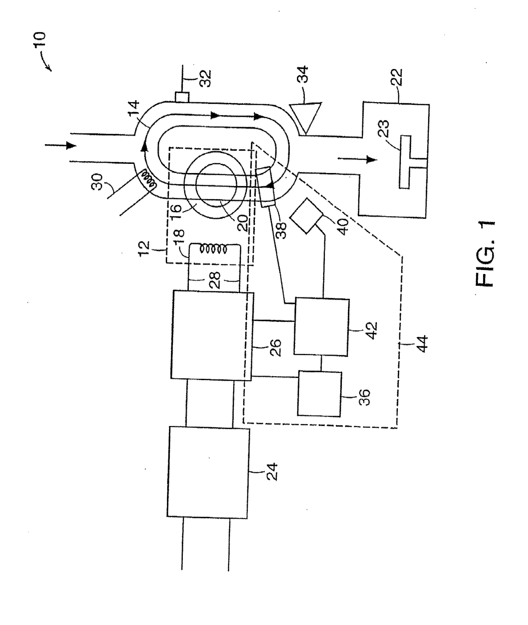
[0043]FIG. 1 is a schematic representation of a plasma source for producing activated gases, according to an illustrative embodiment of the invention. The source 10 includes a power transformer 12 that couples electromagnetic energy into a plasma 14. The power transformer 12 includes a high permeability magnetic core 16, a primary coil 18, and a plasma chamber 20 that contains the plasma 14, which allows the plasma 14 to form a secondary circuit of the transformer 12. The power transformer 12 can include additional magnetic cores and primary coils (not shown) that form additional secondary circuits.

[0044]One or more sides of the plasma chamber 20 are exposed to a process chamber 22 to allow charged particles and activated gases generated by the plasma 14 to be in direct contact with a material to be processed (not shown). A sample holder 23 can be positioned in the process chamber 22 to support the material to be processed. The material to be processed can be biased relative to the ...


PUM


Abstract

An apparatus for abatement of gases is provided. The apparatus includes a toroidal plasma chamber having a plurality of inlets and an outlet, and at least one chamber wall. One or more magnetic cores are disposed relative to the toroidal plasma chamber. The plasma chamber confines a toroidal plasma. A second gas inlet is positioned on the toroidal plasma chamber between a first gas inlet and the gas outlet at a distance d from the gas outlet, such that a toroidal plasma channel volume between the first gas inlet and the second gas inlet in the is substantially filled by the inert gas, the distance d based on a desired residence time of the gas to be abated.

Description

CROSS REFERENCE TO RELATED APPLICATIONS[0001]This application claims the benefit of and priority to U.S. Provisional Patent Application No. 61 / 783,360, filed Mar. 14, 2013, the entire contents of which is owned by the assignee of the instant application and incorporated herein in its entirety.FIELD OF THE INVENTION[0002]The invention relates generally to the field of process gas abatement. More specifically, the invention relates to apparatuses for and methods of abating process gas using a toroidal plasma.BACKGROUND OF THE INVENTION[0003]In semiconductor processes such as etching and chemical vapor deposition, chemically reactive gases can be used during processing or produced as a result of processing. These toxic or otherwise harmful process gases can be treated or abated before their release to atmosphere. A number of technologies have traditionally been used for the abatement of such gases. For example, thermal abatement processes are commonly implemented by burning halogen-con...

Claims


Application Information

Patent Timeline
IPC IPC(8): B01D53/76
CPCB01D53/76B01D53/323B01D2257/2064H01J37/32339H01J37/32357H01J37/32449H01J37/32458H01J37/32651H01J37/32669H01J37/32844H01J37/32935H05H1/46H05H1/4652H05H2245/15Y02C20/30H01J2237/3321H01J2237/334
Inventor CHEN, XINGPOKIDOV, IIYATIAN, ARTHURTRAN, KENLAM, DAVIDWENZEL, KEVIN W.
Owner MKS INSTR INC
Why Eureka
Try Eureka