Visor and method of manufacture

a technology of visor and manufacturing method, which is applied in the field of visors, can solve the problems of reducing reducing the light transmission and optical quality, and requiring costly helmet revisions to the shell and inner lining, so as to avoid reflection, refraction, dirt and moisture ingress, and the effect of increasing the thickness of the visor

Inactive Publication Date: 2014-09-18
PINLOCK PATENT
View PDF5 Cites 40 Cited by
  • Summary
  • Abstract
  • Description
  • Claims
  • Application Information

AI Technical Summary

Benefits of technology

The patent describes a visor for a helmet that has a removable insert with high impact resistance. The insert is made of polycarbonate, which is commonly used for helmet visors due to its excellent engineering properties and optical properties. However, other alternatives such as acrylic based polymers or polyurethane can also be used. The insert can be attached and detached at will using mechanical attachment provisions. The insert is fused or melted with the shield to form an integral unit, which ensures a seamless join and prevents reflections, refraction, dirt and moisture ingress, sharp edges, and other issues. The insert has a thickness of 0.3 mm to 0.7 mm and is curved to match the radius of the shield. The insert also has a photochromatic layer that is protected and supported by an outer protective layer made of a second plastic material. The photochromatic layer comprises a photochromatic pigment incorporated in a polymer matrix.

Problems solved by technology

Driving in bright sunlight, especially when it has rained, or at sunrise or sunset can be hazardous but driving with a tinted visor at night is also dangerous and in many countries is illegal.
Nevertheless, such arrangements are often bulky and complicated and may require costly helmet revisions to the shell and inner lining.
Nevertheless, the integration of such pigments into a visor is complicated.
Pigments introduced directly into the material forming the visor do not function adequately for various reasons.
UVB light in the range 280 nm to 315 nm is particularly damaging for many polymers and UV stabilizers are used to remove these wavelengths.
Even though the photochromatic pigments may be sensitive to other wavelengths outside this range, the overall effectiveness of the pigment is reduced.
Nevertheless, due to their position behind the visor such inserts only partially darken.
This allows an existing visor to be easily adapted but once applied, subsequent removal of the film is likely to leave the visor impaired.
Films applied in this manner are also often subject to peeling and may become unsightly.
Furthermore, many photochromatic pigments are adversely affected by moisture and such films do not always provide adequate protection in this sense, causing accelerated degradation of the pigments.
Although these solutions appear to provide a suitable way of attaching a photochromatic layer to a visor, they do not address the problems of ensuring adequate operation of the photochromatic pigments while avoiding photo-degradation of the visor material.
They also fail to address the problems of injection moulding the visor and the film in a single process.
The heat required during injection moulding can cause many photochromatic pigments to be irreparably damaged.
Manufacture of visors is a relatively costly exercise in that each visor must be injection moulded in an expensive, custom made two-part mould.
A major factor in the expense of the mould is the high quality finish on the inner mould surface.
Although once produced, a single mould may be used for many thousands of visors, each change in shape or detail will require manufacture of a new mould at considerable expense.

Method used


Image

  • Visor and method of manufacture
  • Visor and method of manufacture
  • Visor and method of manufacture

Examples


Embodiment Construction

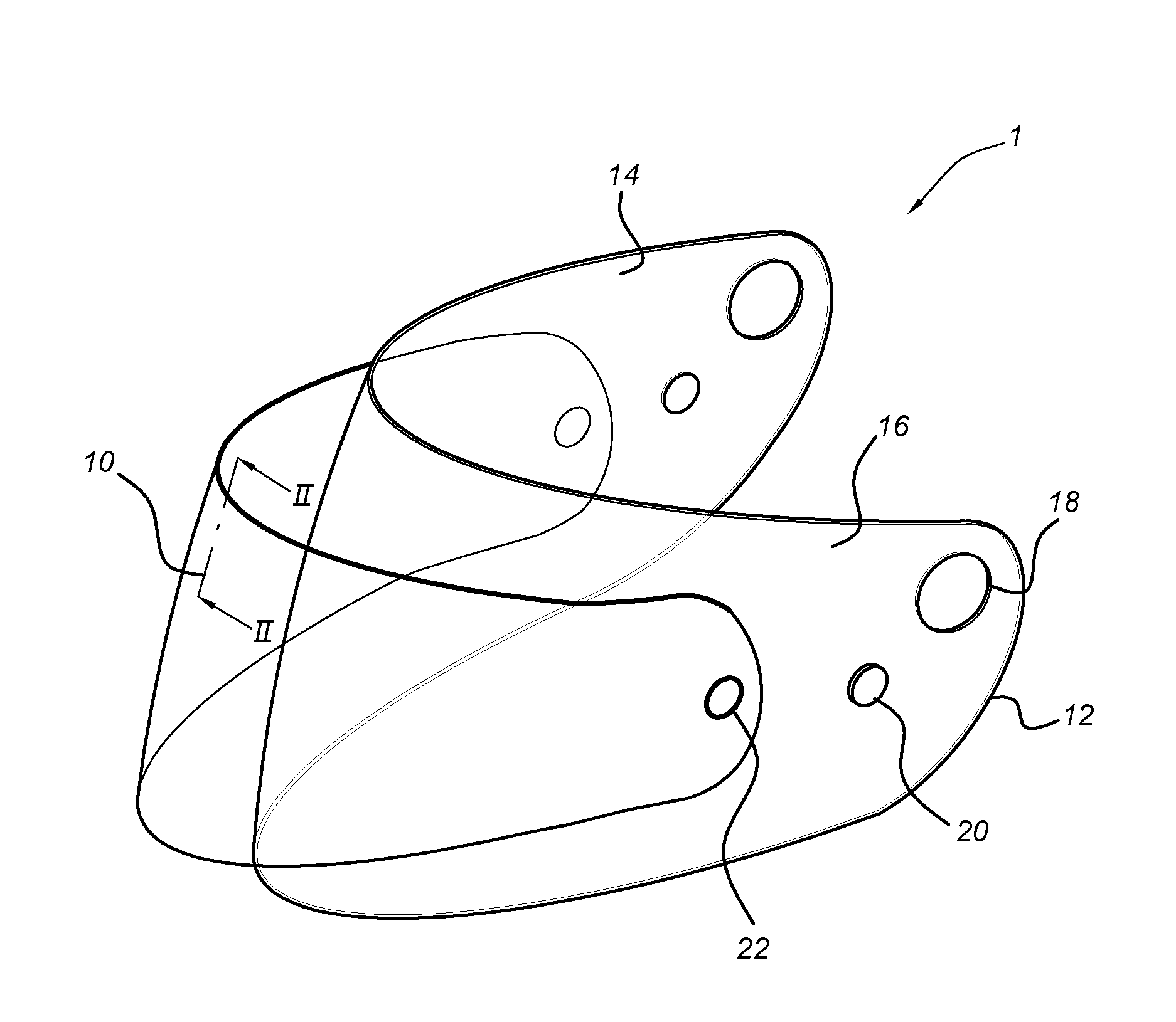
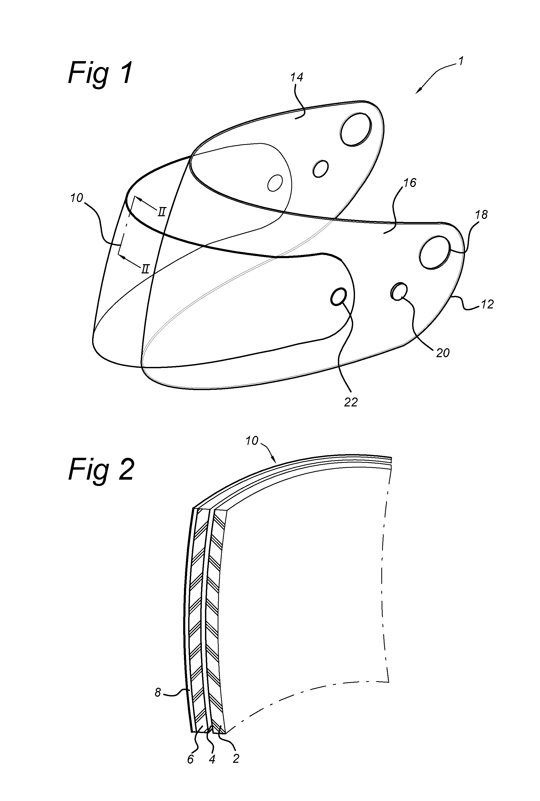
[0034]FIG. 1 shows a perspective view of a visor according to the present invention in an exploded view. The visor 1 is intended for a motorcycle helmet (not shown) and comprises a curved, transparent shield 12 having an inner surface 14 and an outer surface 16. The shield is provided with attachment elements 18 for connecting the visor 1 to the helmet and magnetic studs 20. The shield 12 is otherwise conventional in construction and is formed of polycarbonate material having a quantity of UV stabilizing additives sufficient to prevent discoloration of the visor during normal daytime use. The shield 12 has a thickness of around 2 mm. A photochromatic insert 10 is provided located in front of the shield outer surface 16. The insert 10 is also transparent and curved to match the shield 12. The insert 10 is provided with magnetic disks 22.

[0035]FIG. 2 shows a partial cross-section taken through the insert 10 of FIG. 1. As can be seen, the insert 10 comprises an interface layer 2, an in...


PUM

PropertyMeasurementUnit
thicknessaaaaaaaaaa
thicknessaaaaaaaaaa
thicknessaaaaaaaaaa

Abstract

A visor for a helmet or the like has a curved, transparent shield with an inner surface and an outer surface. The shield is provided with attachment elements for connecting the visor to the helmet and further includes a viewing region having a photochromatic insert at its outer surface, capable of responding to incident light. The shield is formed of a first plastic material provided with an amount of UV stabilizing additives, the UV stabilizing additives protecting the first plastic material from degradation by UV radiation during use, and the insert includes a second plastic material without UV stabilizing additives or having substantially less UV stabilizing additives than the first plastic material. A manufacturing process for producing a visor with a functional insert region is also disclosed.

Description

BACKGROUND OF THE INVENTION[0001]1. Field of the Invention[0002]The present invention relates to visors, in particular to visors provided with photochromatic regions that can change colour or shade in reaction to incident light. The invention further relates to methods of manufacturing visors comprising active elements integrally moulded therewith. Such visors are particularly applicable to helmets such as motorcycle helmets and the like.[0003]2. Description of the Related Art[0004]It has long been desired to provide visors for helmets that can automatically change colour in response to incident light conditions. Driving in bright sunlight, especially when it has rained, or at sunrise or sunset can be hazardous but driving with a tinted visor at night is also dangerous and in many countries is illegal. Some helmets are provided with a secondary pull-down tinted visor or sun-strip that can partially overcome these inconveniences. Nevertheless, such arrangements are often bulky and co...

Claims


Application Information

Patent Timeline
Patent Type & Authority Applications(United States)
IPC IPC(8): A42B3/22
CPCA42B3/225A42B3/226B29D11/00009B29D11/0073B29C45/1418B29C45/1671G02B5/23
Inventor ARNOLD, DEREK LESLIE
Owner PINLOCK PATENT
Why Eureka
Try Eureka