
Anode for secondary battery and secondary battery having the same

a secondary battery and anode technology, applied in the field of anodes, can solve the problems of short circuit, secondary battery cylindrical shape, and limited development of various shapes of mobile devices, and achieve the effects of enhancing battery performance, easy diffusion, and increasing surface area

Active Publication Date: 2014-06-19
LG ENERGY SOLUTION LTD
View PDF0 Cites 16 Cited by
  • Summary
  • Abstract
  • Description
  • Claims
  • Application Information

AI Technical Summary

Benefits of technology

The present invention provides an anode for batteries that has a thin active material layer and a conductive layer on its surface. This design improves the performance of batteries by facilitating the diffusion of Li ions and increases the surface area for reaction with Li ions. The conductive layer prevents release of the anode active material and minimizes side reactions with the electrolyte solution, resulting in improved battery performance.

Problems solved by technology

Because a predetermined mounting space for the electrode assembly is necessary in this process, the cylindrical, prismatic or pouch shape of the secondary batteries has a limitation in developing various shapes of mobile devices.
However, the flexible cable-type secondary batteries are frequently subject to the external physical impact due to their structural characteristics, for example, the twist thereof, which may result in a short circuit.
Further, when Si or Sn is used as an anode active material, the active material may peel off due to the expansion and shrinkage of electrodes caused by the repeated charging and discharging.
Also, when an anode active material layer made of a metal, which is used to increase the capacity of batteries, is thick, it is difficult for lithium ions to diffuse in the anode active material layer, thereby substantially restricting the capacity of batteries.

Method used


Image

  • Anode for secondary battery and secondary battery having the same
  • Anode for secondary battery and secondary battery having the same
  • Anode for secondary battery and secondary battery having the same

Examples


experimental example

Preparation of Coin-Type Half-Cell

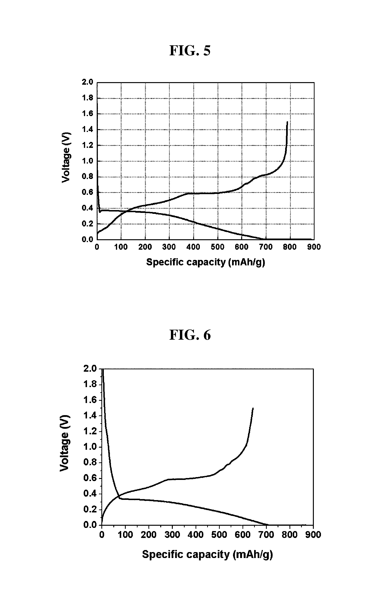
[0069]A lithium foil was used as a cathode and each of the anodes prepared in Example 1 and Comparative Example 1 was used as an anode, and a polyethylene separator was interposed between the cathode and the anode, to obtain an electrode assembly. The electrode assembly was inserted in a battery case, to which an electrolyte solution containing 1M LiPF6 dissolved in a mixed solvent of ethylene carbonate and diethyl carbonate (1:2 (vol %)) was introduced, to prepare a coin-type half-cell battery.

[0070]Each battery using each anode prepared in Example 1 and Comparative Example 1 was charged with a constant current of 0.1 C up to 5 mV and then with a constant voltage of 5 mV, and the charging process for each battery was completed when the charging current reached 0.005 C. Each battery was discharged with a constant current of 0.1 C up to 1.5 V. The charging / discharging was repeated 30 times under the same conditions, and then the charging / discharging ...


PUM

PropertyMeasurementUnit
thicknessaaaaaaaaaa
diameteraaaaaaaaaa
constant voltageaaaaaaaaaa

Abstract

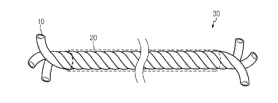
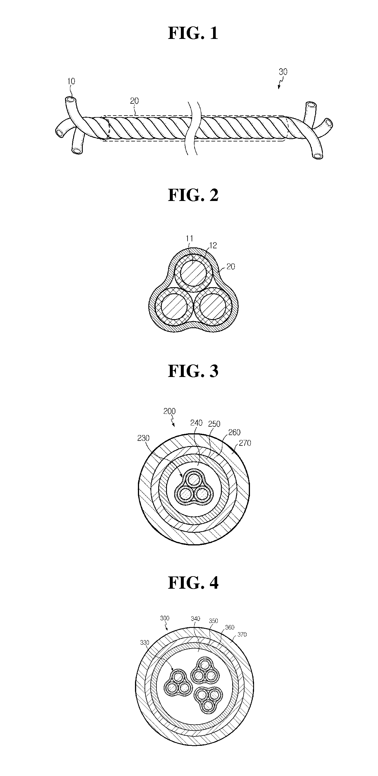
The present invention relates to an anode for a secondary battery, comprising: a spiral anode having at least two anode wires which are parallel to each other and spirally twisted, each of the anode wires having an anode active material layer coated on the surface of a wire-type current collector; and a conductive layer formed to surround the spiral anode.The anode active material layer of the spirally-twisted has a thin thickness as compared with a single strand of an anode having the same anode active material. Therefore, Li ions can be easily diffused to enhance battery performance. Also, the anode of the present invention has a conductive layer on the surface thereof to prevent or alleviate the release of an anode active material which is caused by volume expansion during charging and discharging processes, and to solve the isolation of the anode active material.

Description

CROSS-REFERENCE TO RELATED APPLICATION(S)[0001]This application is a continuation of International Application No. PCT / KR2012 / 008822 filed on Oct. 25, 2012, which claims priority from Korean Patent Application No. 10-2011-0109562 filed in the Republic of Korea on Oct. 25, 2011 and Korean Patent Application No. 10-2012-0118938 filed in the Republic of Korea on Oct. 25, 2012, the disclosures thereof are incorporated herein by reference.TECHNICAL FIELD[0002]The present invention relates to an anode which is suitably used in secondary batteries, more specifically an anode having a spiral anode and a conductive layer, and a secondary battery comprising the anode.BACKGROUND ART[0003]Secondary batteries are devices which store electrical energy in a chemical form and generate electricity when needed. The secondary batteries are also referred to as rechargeable batteries because they can be charged repeatedly. Common secondary batteries include lead accumulators, NiCd batteries, NiMH accumu...

Claims


Application Information

Patent Timeline
Patent Type & Authority Applications(United States)
IPC IPC(8): H01M10/04H01M50/417H01M50/42H01M50/423
CPCH01M10/0431H01M4/13H01M4/661H01M4/663H01M4/668H01M4/75H01M10/052H01M10/0565H01M10/058H01M4/134H01M4/387H01M50/42H01M50/423H01M50/417H01M4/622H01M4/625H01M4/38Y02E60/10Y02P70/50H01M4/02H01M4/64H01M4/36H01M4/62
Inventor KWON, YO-HANOH, BYUNG-HUNJUNG, DONG-SUBKIM, JE-YOUNG
Owner LG ENERGY SOLUTION LTD
Learn More