
Voltage-controlled magnetic memory element with canted magnetization

a magnetic memory element and voltage control technology, applied in the field of magnetic tunnel junctions, can solve the problem of limiting the energy efficiency of spintronic memory and logic devices

Active Publication Date: 2014-06-19
RGT UNIV OF CALIFORNIA
View PDF1 Cites 150 Cited by
  • Summary
  • Abstract
  • Description
  • Claims
  • Application Information

AI Technical Summary

Benefits of technology

The present invention is about a device called a magneto-electric tunnel junction (MEJ) that can be electrically switched using a magnetic field. The device allows for very fast switching between two states without the need for spin-polarized currents. The device can also be controlled by a small magnetic field and can have a high resistance ratio. This technology offers a way to control the magnetization of a device using a voltage, which is useful for various applications such as electronics. The device can be switched using a small external magnetic field, and the switching direction can be controlled by timing the pulse.

Problems solved by technology

The use of currents, however, limits the energy efficiency of spintronic memory and logic devices.

Method used


Image

  • Voltage-controlled magnetic memory element with canted magnetization
  • Voltage-controlled magnetic memory element with canted magnetization
  • Voltage-controlled magnetic memory element with canted magnetization

Examples


experiment # 1

[0056]Experiment #1

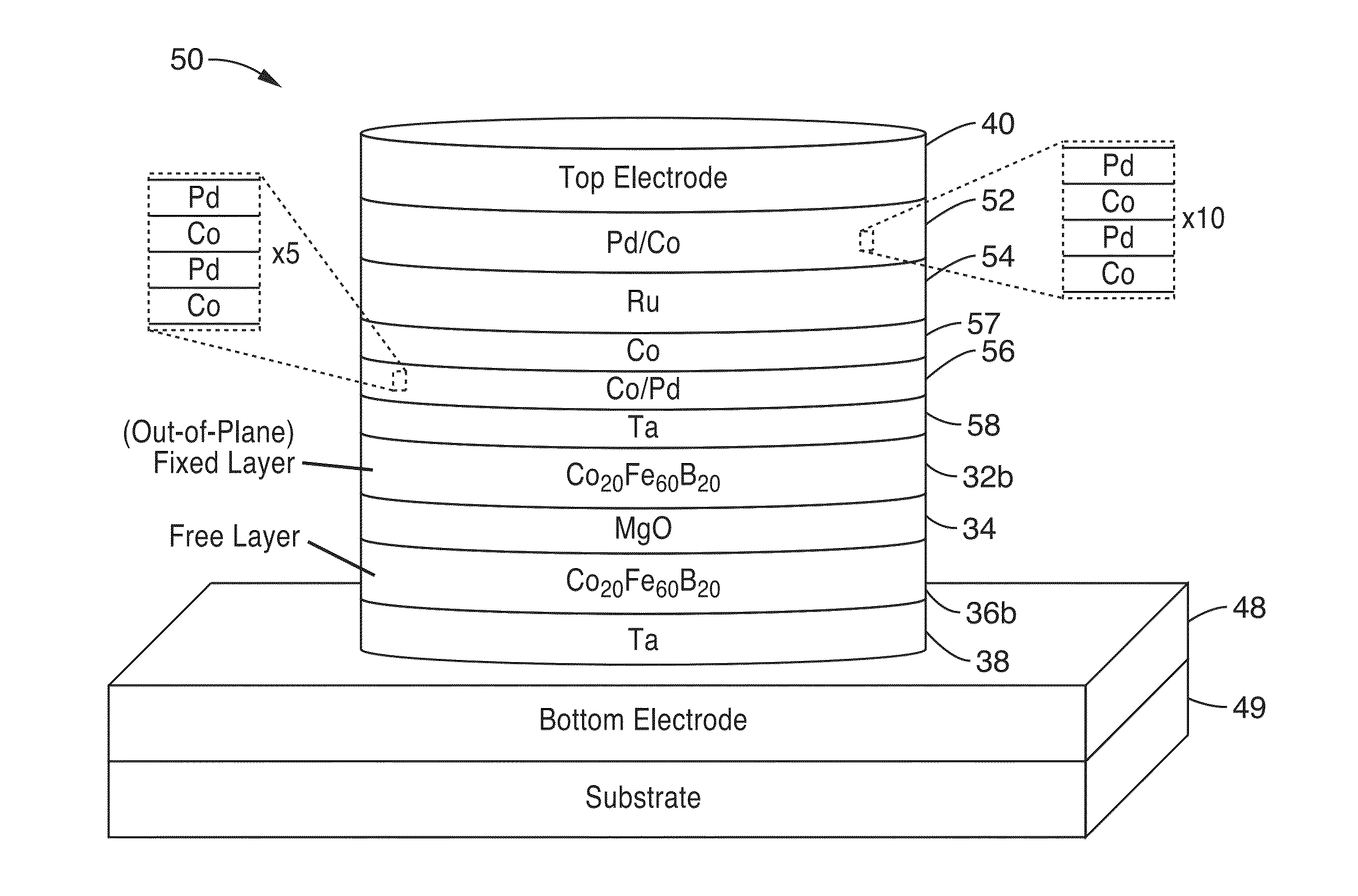
[0057]To test the devices of the present invention detailed above, continuous multilayer films with a composition similar to that shown in FIG. 3A (e.g. substrate 49 / bottom electrode 48 / Ta (5 nm thickness) / Co20Fe60B20 free layer 36a with thickness range(tCoFeB=1.0 nm-1.4 nm wedge) / MgO dielectric layer 34 with thickness range (tMgO=1.2 nm-1.4 nm wedge) / Co60Fe20B20 in-plane fixed layer 32a (2.7 nm thickness) / Ru layer 46 (0.85 nm thickness) / Co70Fe30 layer 44 (2.3 thickness) / PtMn layer 42 (20 nm thickness) / top electrode 40 were deposited in a Singulus TIMARIS physical vapor deposition (PVD) system, and subsequently annealed at 300° C. for 2.0 hours in an in-plane magnetic field of 1 T. The films were then patterned into 170 nm×60 nm elliptical nanopillars for electrical measurements using electron-beam lithography and ion milling techniques. The readout of the state of the free layer is performed via the TMR effect and all the measurements were performed at room tempe...


PUM


Abstract

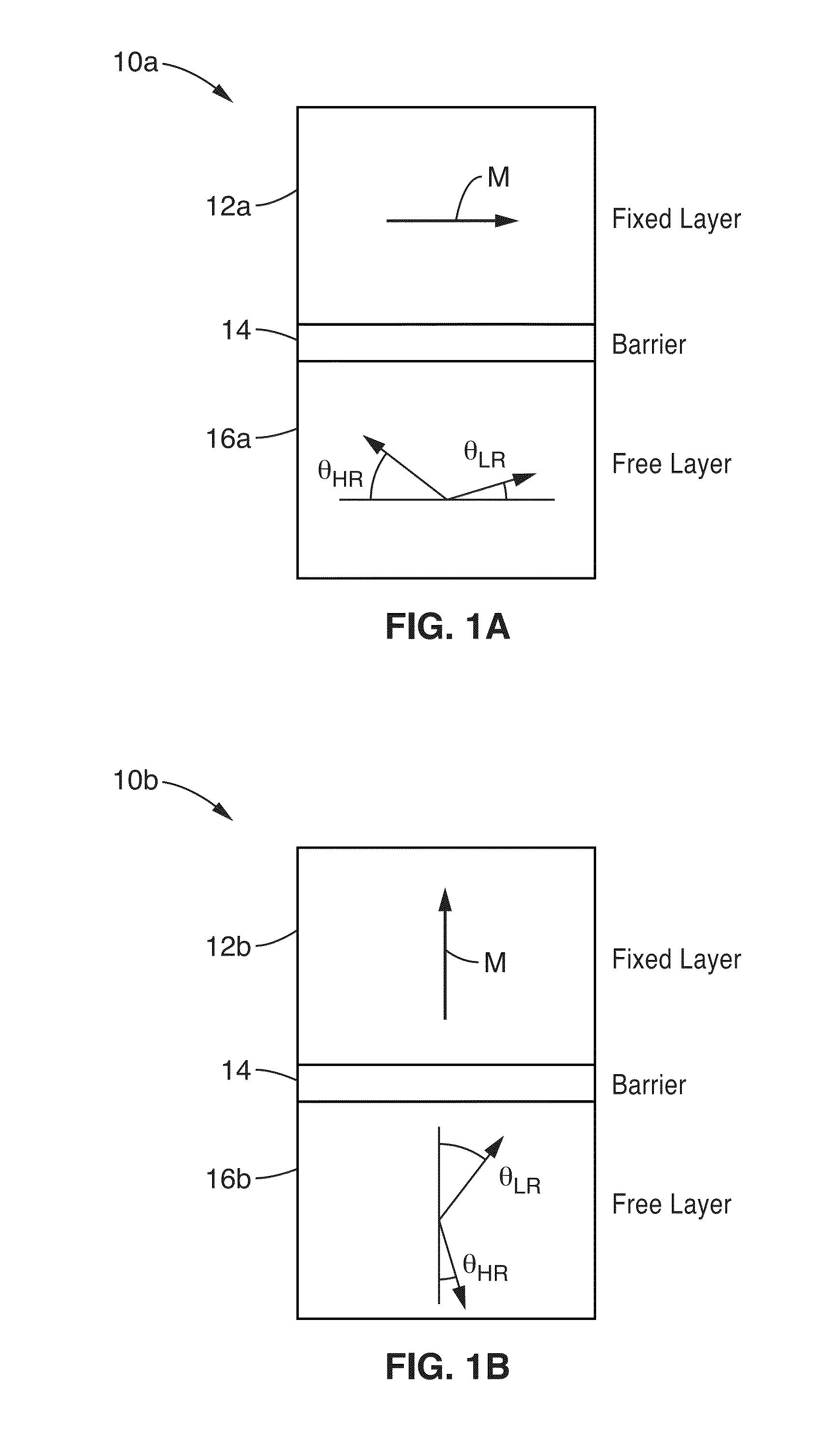
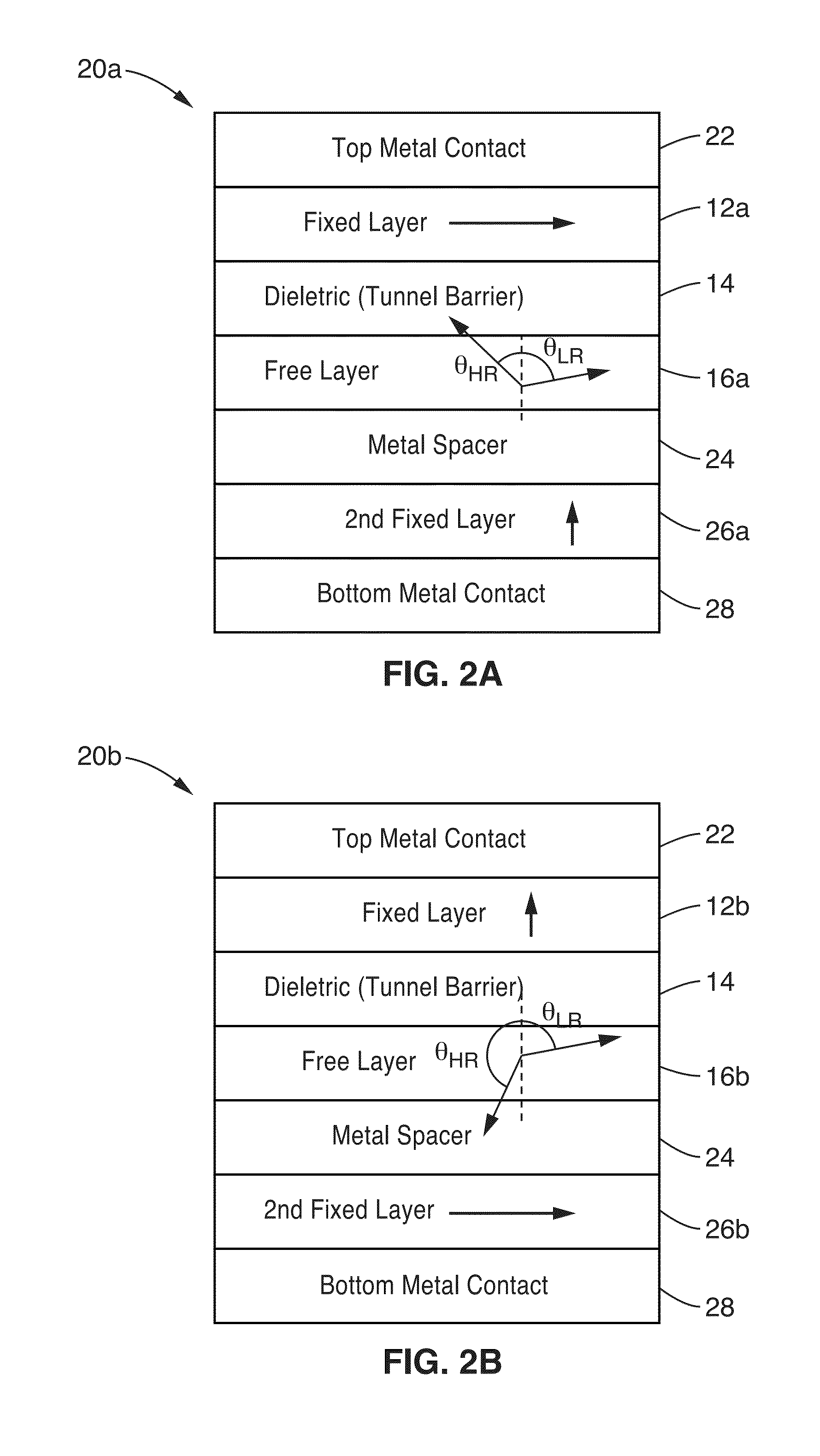
A memory cell including information that is stored in the state of a magnetic bit (i.e. in a free layer, FL), where the FL magnetization has two stable states that may be canted (form an angle) with respect to the horizontal and vertical directions of the device is presented. The FL magnetization may be switched between the two canted states by the application of a voltage (i.e. electric field), which modifies the perpendicular magnetic anisotropy of the free layer.

Description

CROSS-REFERENCE TO RELATED APPLICATIONS[0001]This application is a nonprovisional of U.S. provisional patent application Ser. No. 61 / 734,922 filed on Dec. 7, 2012, incorporated herein by reference in its entirety.INCORPORATION-BY-REFERENCE OF COMPUTER PROGRAM APPENDIX[0002]Not ApplicableSTATEMENT REGARDING FEDERALLY SPONSORED RESEARCH OR DEVELOPMENT[0003]This invention was made with Government support under Grant No. HR0011-10-C-0153 awarded by the Defense Advanced Research Projects Agency (DARPA). The Government has certain rights in this invention.NOTICE OF MATERIAL SUBJECT TO COPYRIGHT PROTECTION[0004]A portion of the material in this patent document is subject to copyright protection under the copyright laws of the United States and of other countries. The owner of the copyright rights has no objection to the facsimile reproduction by anyone of the patent document or the patent disclosure, as it appears in the United States Patent and Trademark Office publicly available file or ...

Claims


Application Information

Patent Timeline
IPC IPC(8): H01L43/02H01L27/22G11C11/16H01L43/10
CPCG11C11/1675G11C11/161H10B61/22H10N50/85H10N50/10
Inventor WANG, KANG L.KHALILI AMIRI, PEDRAMALZATE, JUAN G.
Owner RGT UNIV OF CALIFORNIA
Learn More