
Magnetoresistive sensor having reduced read gap and strong pinned layer stability

a magnetic sensor and read gap technology, applied in the field of magnetic data recording, can solve the problems of large read gap budget, difficult to achieve high read-out resolution or good read-out characteristics, and inability to obtain good read-out characteristics, etc., to achieve high aspect ratio, reduce degradation of mr characteristics, and ensure the effect of output symmetry

Inactive Publication Date: 2014-05-15
HITACHI GLOBAL STORAGE TECH NETHERLANDS BV
View PDF5 Cites 9 Cited by
  • Summary
  • Abstract
  • Description
  • Claims
  • Application Information

AI Technical Summary

Benefits of technology

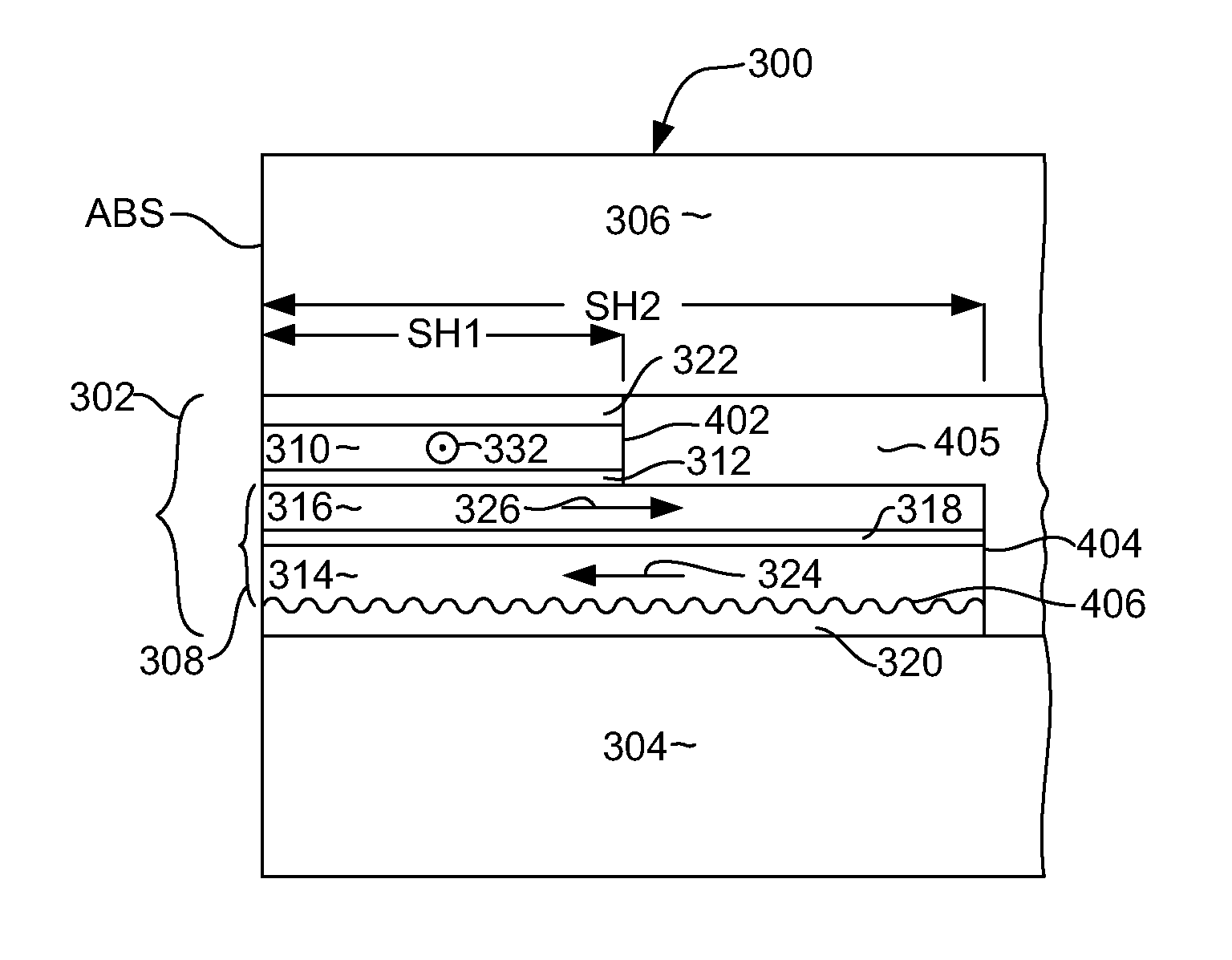
The present invention provides a spin valve magnetic sensor film that can control the direction of magnetization of the pinned layer without using an anti-ferromagnetic layer that would increase gap thickness. The film has a structure that maintains an orthogonal arrangement of the magnetizations of the pinned layer and the free layer, even when the film is exposed to external magnetic fields or temperature changes. The film also has a high resolution and reduced noise, and stable read-out characteristics can be obtained. The technical effects of the invention include a smaller read gap length, improved utilization, and reduced noise.

Problems solved by technology

If the read gap cannot be sufficiently narrowed, that is, a thinner magnetic sensor film cannot be realized, it becomes difficult to achieve a high read-out resolution or good read-out characteristics.
In the thin-film layer structure of the magnetic sensor film, the anti-ferromagnetic layer is the thickest film and, therefore, consumes a large portion of the read gap budget.
Another concern is that good read-out characteristics are not obtained because the stability of the magnetization of the pinned layer near the ABS significantly affects the output characteristics of the magnetic read head.
However, the texture formed on the seed layer affects the anisotropy of the magnetization of the free layer and not just the pinned layer.
In this case, simultaneously controlling the magnetization directions of the pinned layer and the free layer becomes difficult, and obtaining good read-out characteristics becomes difficult.
In addition, in a spin valve magnetic sensor film having a layered structure of extremely thin films, the roughness of the layered interface causes degradation in the magnetoresistive effect (MR) characteristics and leads to an increase in the interlayer interaction between the magnetization of the pinned layer and the magnetization of the free layer.
Consequently, this is undesirable from the perspectives of the read-out sensitivity and ensuring symmetry in the output.
Previous attempts at minimizing the gap thickness, such as by reducing or eliminating the AFM layer in the sensor stack, have not been able to achieve all of these goals.

Method used


Image

  • Magnetoresistive sensor having reduced read gap and strong pinned layer stability
  • Magnetoresistive sensor having reduced read gap and strong pinned layer stability
  • Magnetoresistive sensor having reduced read gap and strong pinned layer stability

Examples


Embodiment Construction

[0020]The following description is of the best embodiments presently contemplated for carrying out this invention. This description is made for the purpose of illustrating the general principles of this invention and is not meant to limit the inventive concepts claimed herein.

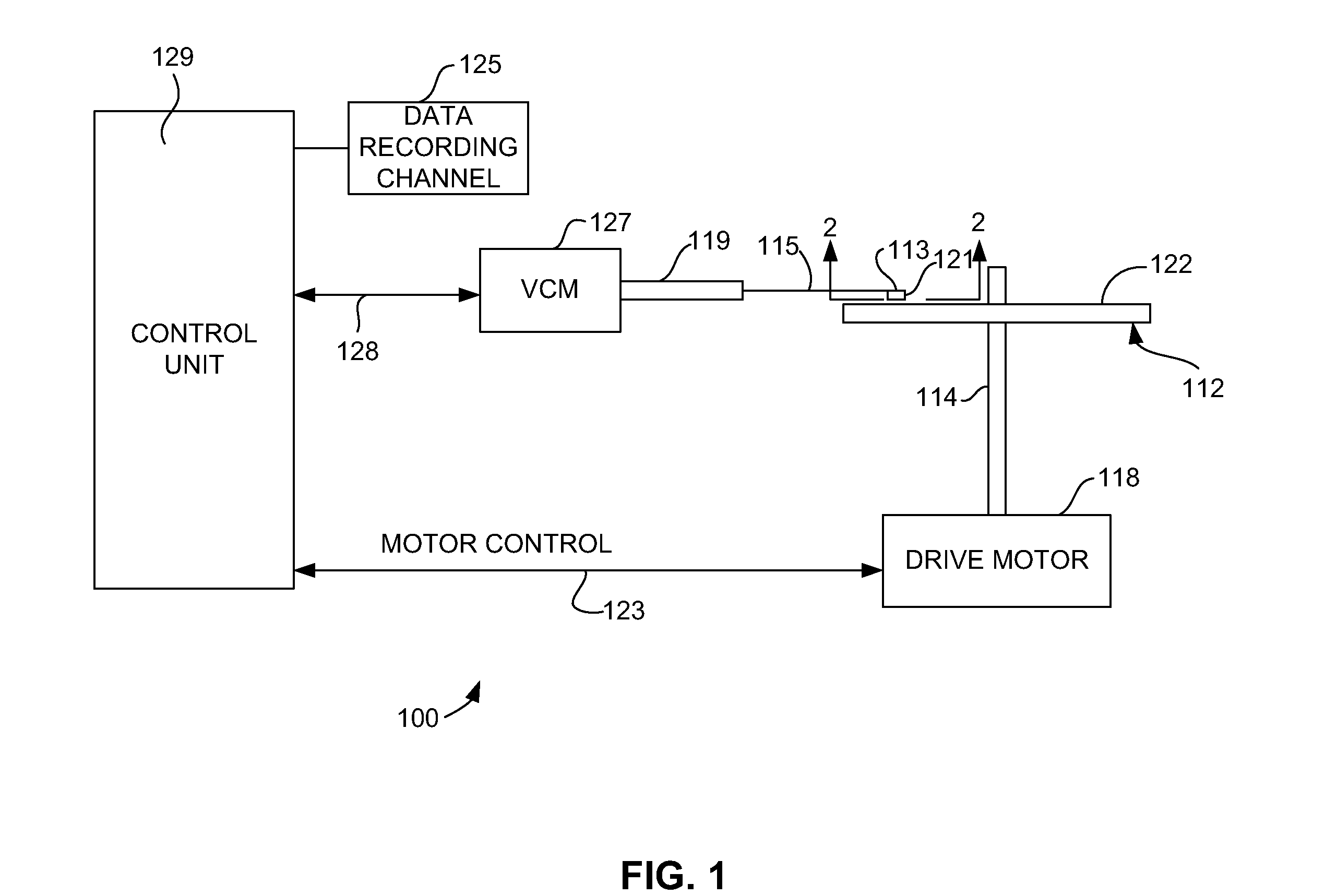
[0021]Referring now to FIG. 1, there is shown a disk drive 100 embodying this invention. As shown in FIG. 1, at least one rotatable magnetic disk 112 is supported on a spindle 114 and rotated by a disk drive motor 118. The magnetic recording on each disk is in the form of annular patterns of concentric data tracks (not shown) on the magnetic disk 112.

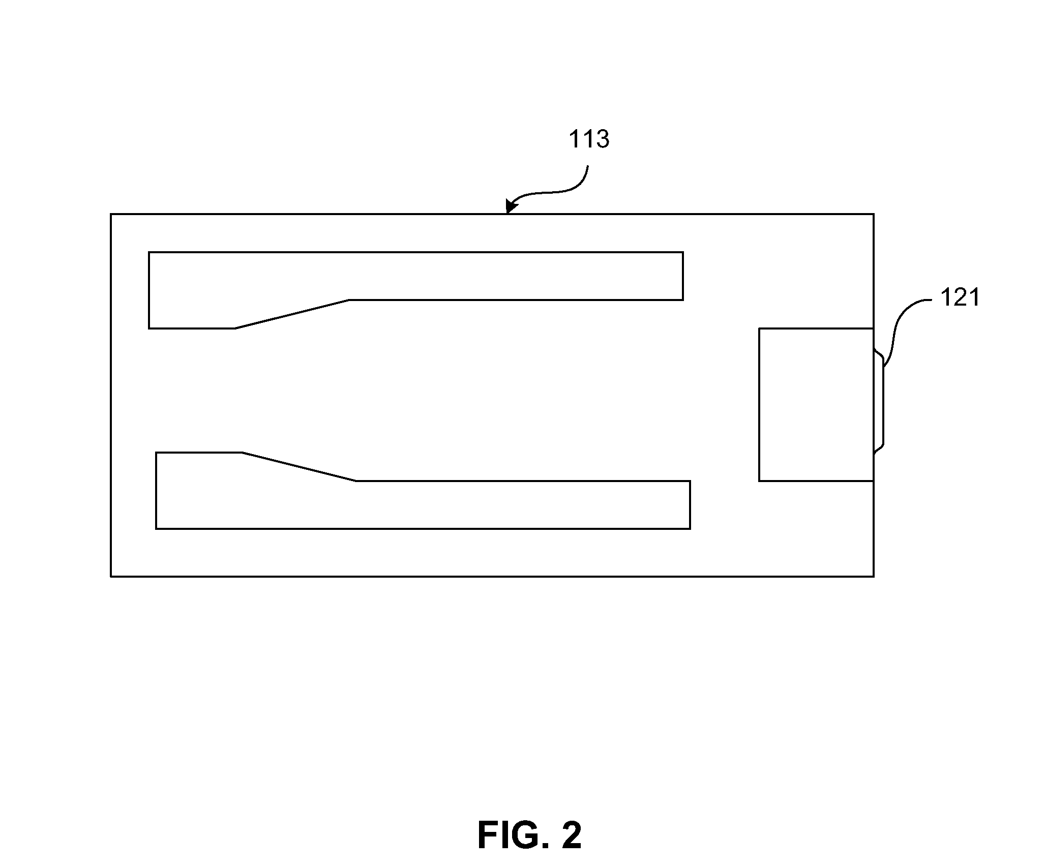
[0022]At least one slider 113 is positioned near the magnetic disk 112, each slider 113 supporting one or more magnetic head assemblies 121. As the magnetic disk rotates, slider 113 moves radially in and out over the disk surface 122 so that the magnetic head assembly 121 can access different tracks of the magnetic disk where desired data are written. Each slider 1...


PUM

PropertyMeasurementUnit
thicknessaaaaaaaaaa
thicknessaaaaaaaaaa
read gap lengthaaaaaaaaaa

Abstract

A magnetic read head having a reduced read gap and a stable magnetic pinned layer structure. The sensor includes a seed layer that has a surface formed with an anisotropic texture. A magnetic pinned layer formed over the seed layer has a body centered cubic structure which causes the pinned layer structure to have a magnetic anisotropy with an easy axis oriented perpendicular to the air bearing surface when deposited over the textured seed layer. A magnetic free layer structure formed over the pinned layer structure and over a non-magnetic barrier layer has a face centered cubic structure which causes the magnetic free layer to have a magnetic anisotropy with an easy axis oriented parallel with the air bearing surface.

Description

FIELD OF THE INVENTION[0001]The present invention relates to magnetic data recording and more particularly to a read sensor structure having a pinning structure that has robust pinned layer pinning without the use of an antiferromagnetic layer, thereby achieving a reduced read gap thickness.BACKGROUND OF THE INVENTION[0002]The market for information storage and recording devices is steadily expanding, supported by the development of devices that require the storage of vast amounts of data. Within these developments, demand is every growing for the development of technologies for achieving higher recording densities in Hard Disk Drives (HDDs). In the corresponding technology trends, current HDDs have moved from in-plane magnetic recording techniques to perpendicular magnetic recording techniques, and the playback magnetic head mounted in the HDD is shifting from a current-in-the-plane, giant magneto-resistive (CIP-GMR) heads to tunneling magnetoresistive (TMR) heads which have high r...

Claims


Application Information

Patent Timeline
Patent Type & Authority Applications(United States)
IPC IPC(8): G11B5/127G11B5/39
CPCG11B5/398G11B5/127G11B5/3906G11B5/3909G11B5/3929Y10T428/1121
Inventor MEGURO, KENICHIKATO, KEIZOOKAMURA, SUSUMUYOSHIDA, NOBUO
Owner HITACHI GLOBAL STORAGE TECH NETHERLANDS BV
Learn More