
Apparatus and method for targeting a body tissue

a body tissue and appendix technology, applied in the field of appendix and method for targeting a body tissue, can solve the problems of difficulty in obtaining stable catheter positioning, no device currently available that allows safe puncture, and difficult applicability of left ventricl

Active Publication Date: 2014-04-24
THE CLEVELAND CLINIC FOUND +1
View PDF4 Cites 3 Cited by
  • Summary
  • Abstract
  • Description
  • Claims
  • Application Information

AI Technical Summary

Benefits of technology

The present invention describes an apparatus for targeting a desired target site on a body tissue of a patient. The apparatus includes a target catheter with a longitudinally extending target catheter lumen surrounded by a tubular target catheter wall having an outer surface. A framing member is inserted into the first body cavity and expanded to place within the cavity. The framing member has a longitudinally extending target catheter lumen surrounded by a tubular framing member body with a maximum body footprint and a smaller diameter at the distal ends. The framing member has a plurality of longitudinally extending multi-segment framing strands with interposed strand hinges. The framing strands are connected to the framing member core with slidable ends. The framing member is designed to resist movement in the first body cavity and can be used to deliver a target point to the desired target site. The target pathway extends through the target catheter lumen and is substantially spaced apart from the framing member body. The technical effect of this invention is to provide a reliable and effective apparatus for targeting a desired target site on a body tissue of a patient.

Problems solved by technology

Approaches from the left ventricle are difficult, may cause arrhythmias, and may present difficulty in obtaining stable catheter positioning.
There is no device currently available that allows safe puncture from the superior vena cava 106.
A variety of risks are attendant to transseptal catheterization, in addition to the risks associated with normal heart catheterization.
Such inaccuracy may increase procedure time and / or create a risk that the needle will pierce a heart structure in an unnecessary and potentially undesirable location.
Another problem is that the needle may slip while advancing toward the interatrial septum 110, resulting in an inadvertent puncture into surrounding structures within / defining the right atrium 102 before the needle even reaches the interatrial septum 110.

Method used


Image

  • Apparatus and method for targeting a body tissue
  • Apparatus and method for targeting a body tissue
  • Apparatus and method for targeting a body tissue

Examples


first embodiment

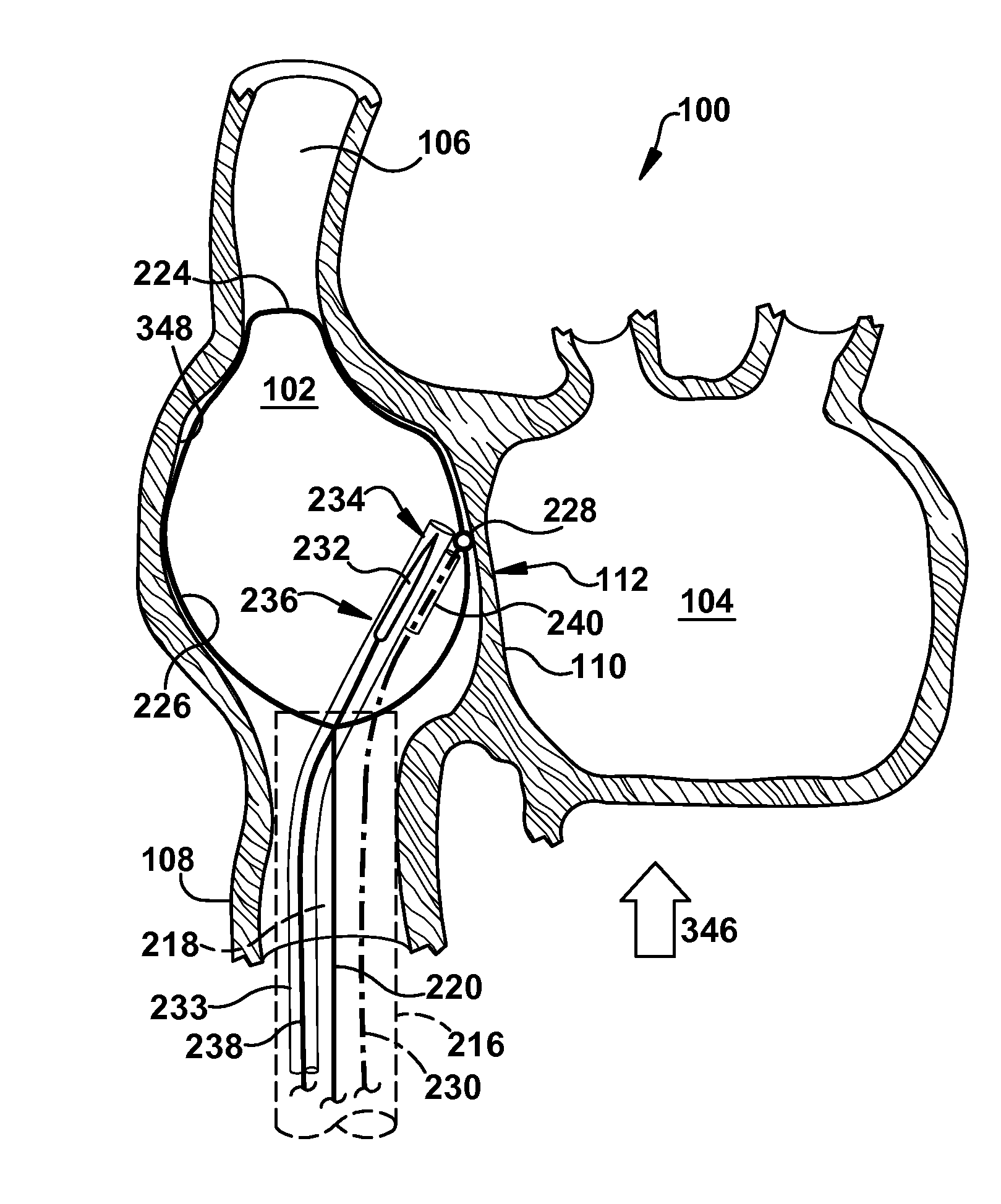
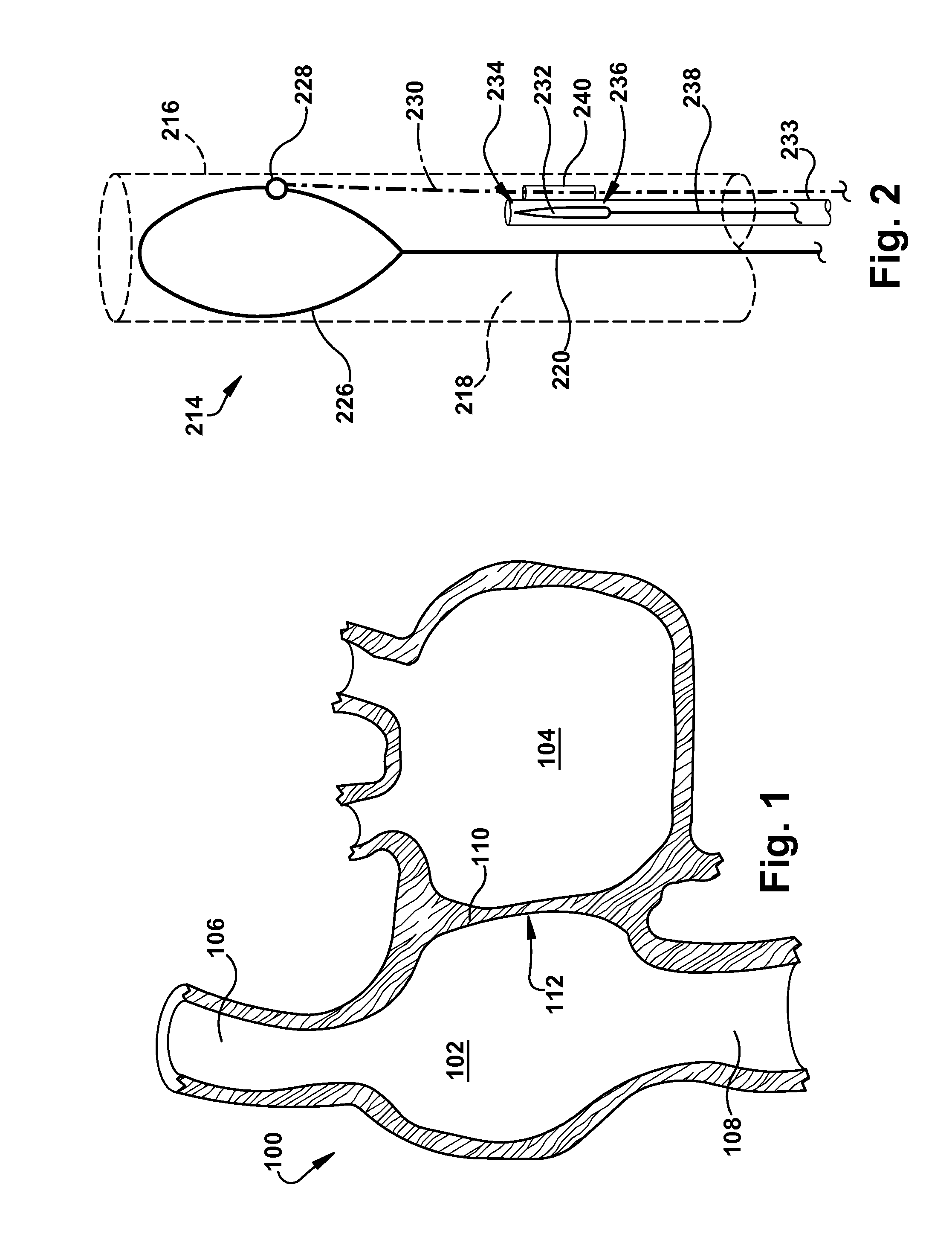
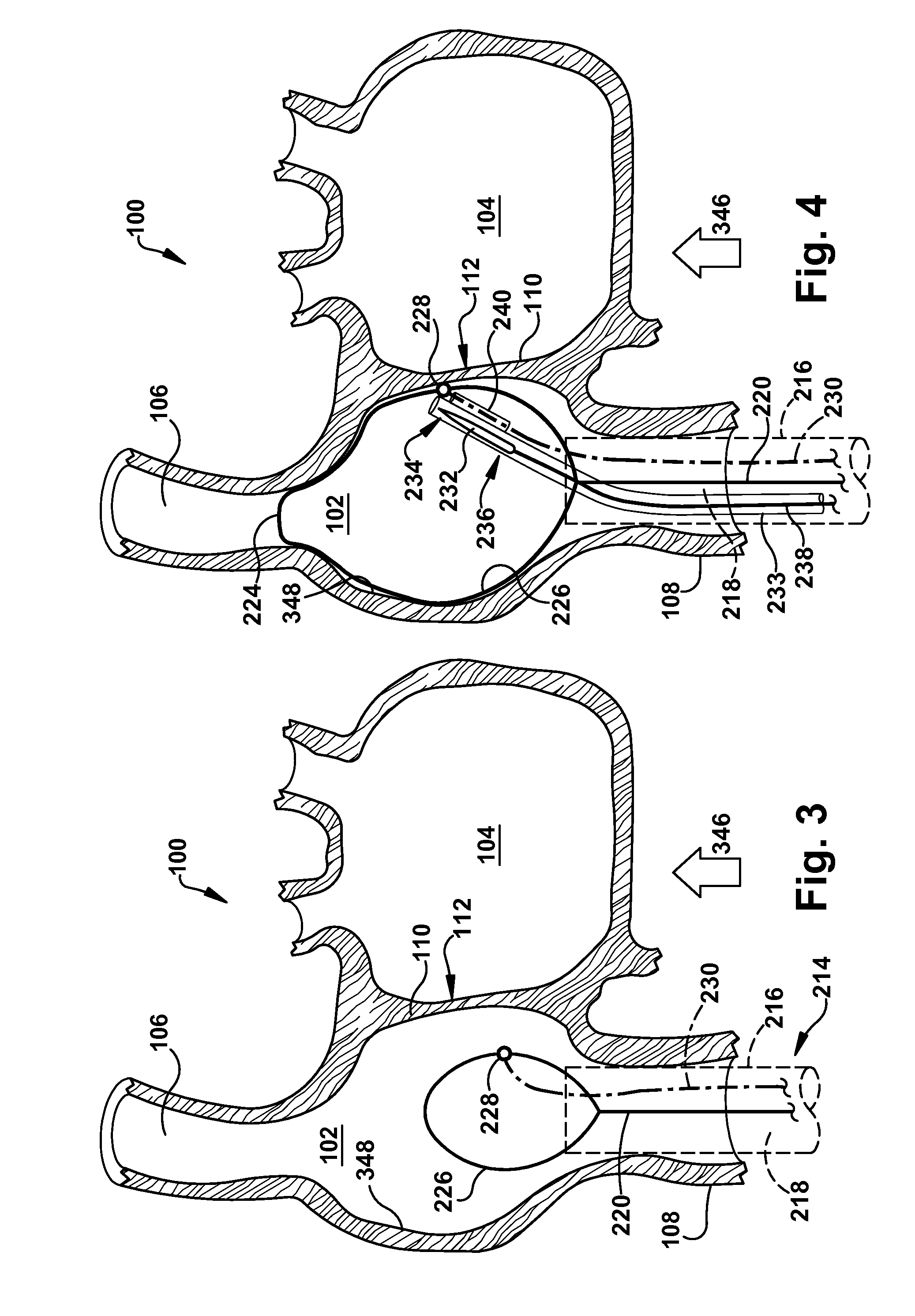
[0067]In accordance with the present invention, FIG. 2 depicts an apparatus 214 for targeting a desired target site on a body tissue. Throughout this description, the desired target site is presumed to be an interatrial septum 110 that separates a right atrium 102 from a left atrium 104 of a heart 100, but (as discussed below) may be any body tissue of a patient. Moreover, this description presumes that the desired target site is being targeted for puncture. However, the apparatus 214 could be useful in precisely locating a desired target site which is being targeted for any reason, without limitation. For example, it may be useful to target a desired target site without necessarily puncturing or otherwise altering the target site when repairing an atrial septum defect (such as a patent foramen ovalis), for dissection / location / alignment of any body structure, when repairing a perivalvular leak, for pinpointing a small branch from a blood vessel (i.e., targeting a void in a body tiss...

fourth embodiment

[0105]The framing member 220d of the fourth embodiment has a flat, elongated ribbon-like structure, at least for the planar framing member body 226d portion thereof. The framing member 220d may be self-expanding, but is not necessarily so. The first and second framing member ends (not shown) may be of any suitable configuration. A plurality of target points 228d are arranged in a target grid 656d on a planar surface of the framing member body 226d. Target wires 230d may connect one or more target points 228d with one or more external power sources, for ease of location of the respective target points 228d within the right atrium.

[0106]The framing member 220d may be at least partially perforated or formed from mesh, an example portion of which is shown in dotted line in FIG. 15, to allow for the puncture needle or other structures to easily extend and / or pass through the thickness of the framing member 220d.

[0107]The framing member 220d of the fourth embodiment may be deployed simil...

fifth embodiment

[0109]The apparatus 214e of the fifth embodiment includes a framing member 220e having a plurality of framing strands 652e connected by flexible framing cross members 654e. The framing strands 652e are self-expanding and are arranged to draw the framing cross members 654e taut in the second, expanded condition. The framing member 220e is held in a compressed configuration to fit within the catheter 216e in the first, collapsed condition.

[0110]The framing member 220e supports a plurality of target points 228e in a target grid 656e. Any number of target points 228e may have an associated target wire 230e. Unlike the previously described embodiments, the target grid 656e is located at or near the first framing member end 1058e of the framing member 220e in the fifth embodiment.

[0111]To deploy the framing member 220e of the fifth embodiment, the framing member and catheter 216e are relatively moved, such as by extending the framing member in the advancement direction 346e. As depicted i...


PUM


Abstract

An apparatus for targeting a desired target site on a body tissue comprising a wall of a first body cavity of a patient includes a target catheter. The framing member has a longitudinal framing member core defining a central framing member axis. At least one target point is carried by the framing member and is adapted for placement adjacent the desired target site. The framing member comprises a plurality of longitudinally extending multi-segment framing strands.

Description

RELATED APPLICATIONS[0001]This application claims priority from U.S. Provisional Patent Application Ser. No. 60 / 850,147, filed 6 Oct. 2006; U.S. patent application Ser. No. 11 / 867,774, filed 5 Oct. 2007 (now U.S. Pat. No. 8,019,404, issued 13 Sep. 2011); U.S. patent application Ser. No. 13 / 206,639, filed 10 Aug. 2011; U.S. Provisional Patent Application Ser. No. 61 / 716,690, filed 22 Oct. 2012; U.S. Provisional Patent Application Ser. No. 61 / 716,693, filed 22 Oct. 2012; U.S. Provisional Patent Application Ser. No. 61 / 716,699, filed 22 Oct. 2012; U.S. Provisional Patent Application Ser. No. 61 / 716,705, filed 22 Oct. 2012; U.S. Provisional Patent Application Ser. No. 61 / 716,716, filed 22 Oct. 2012; U.S. Provisional Patent Application Ser. No. 61 / 716,723, filed 22 Oct. 2012; all of which are titled “Apparatus and Method of Targeting a Body Tissue”; and U.S. Provisional Patent Application Ser. No. 61 / 716,651, filed 22 Oct. 2012 titled “Method and Apparatus for Insertion into a Body Cavit...

Claims


Application Information

Patent Timeline
IPC IPC(8): A61M5/42
CPCA61M5/427A61B17/3403A61B17/3478A61B2017/00243A61B2017/00247A61B2017/00252A61B2017/22069A61B2017/3488A61B2017/3405A61B2017/3411A61B2017/22095A61B2018/00279A61B2018/00357A61B2018/0038A61B2018/00386A61B2018/00351A61B34/20A61B2034/2051
Inventor KAPADIA, SAMIRBERRADA, MARWANEFUENTES-ORTEGA, CESARMOK, DANIEL WING FAI
Owner THE CLEVELAND CLINIC FOUND
Learn More