Method and apparatus to produce high density overcoats

Inactive Publication Date: 2014-04-17
INTEVAC
View PDF9 Cites 9 Cited by
  • Summary
  • Abstract
  • Description
  • Claims
  • Application Information

AI Technical Summary

Benefits of technology

The invention enables a high deposition rate, high target utilization, controlled plasma interaction with the growing film, and reduced neutral recoil or negative ion induced damage on the substrate. It is useful in various applications and is especially beneficial for depositing DLC coating, ITO deposition, and improving CIGS / CIS sputter quality. A deposition system is provided where conductive targets of similar composition are situated opposing each other, which generates a "plasma cage" wherein the carbon atoms collide with accelerating electrons and get highly ionized. The electrons are trapped inside the plasma cage, while the ionized carbon atoms are deposited on the surface of the substrate. No substrate damage or heating occurs, and the embodiments are designed such that argon atoms, which are used to ignite and sustain the plasma, do not reach the substrate, as to avoid damaging it.

Problems solved by technology

One formidable obstacle to realizing this design in manufacturing is the reality that current hydrogenated diamond like carbon (DLC) overcoats are likely to become graphitized under the persistent exposure to elevated temperatures and, thus, lose their protective quality.
Unfortunately, the FCA technique brings with it inherent problems including compatibility with the installed base of disc processing equipment, a process prone to high counts of particulates, and poor scalability to accommodate various sizes of substrates and carrier panels.

Method used


Image

  • Method and apparatus to produce high density overcoats
  • Method and apparatus to produce high density overcoats
  • Method and apparatus to produce high density overcoats

Examples


example i

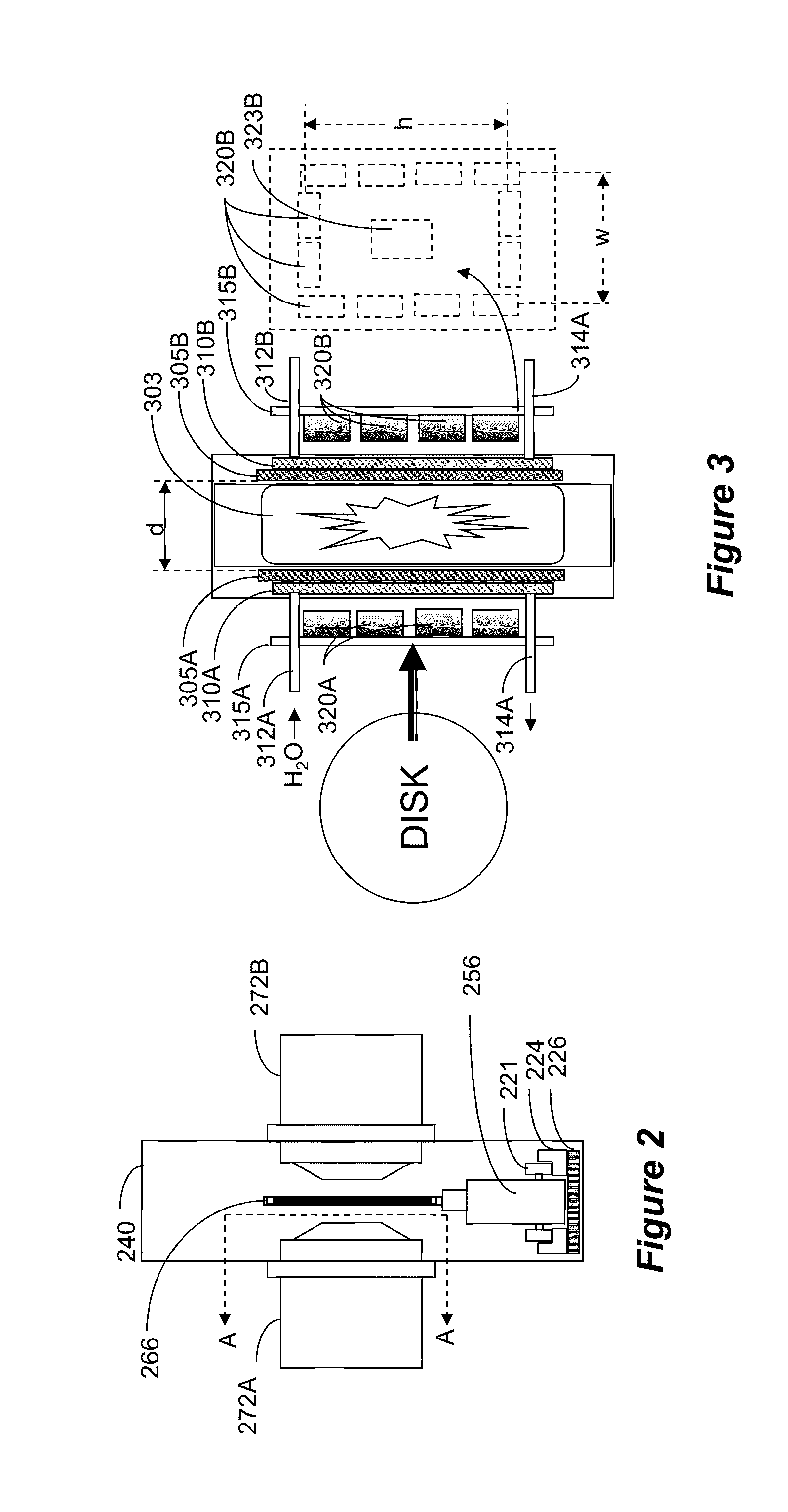
[0034]In a first example, a plurality of 354 kJ / m3 magnets are placed upon a 410 stainless steel mounting plate, which is subsequently attached directly behind each target's heatsink. The outer ring of magnets all have the same polarity, and the opposite polarity to the magnet plate constructed for the opposing target. An optional field-bending magnet 323B is added at the center of the mounting plate, so as to bend the magnetic field generated by the outer ring of magnets 320B. This provides an improved confinement of the plasma. In this example, an equal or weaker magnet 323B (BHmax≦354 kJ / m3) of opposite polarity of magnets 320B is interposed within the outer ring.

example ii

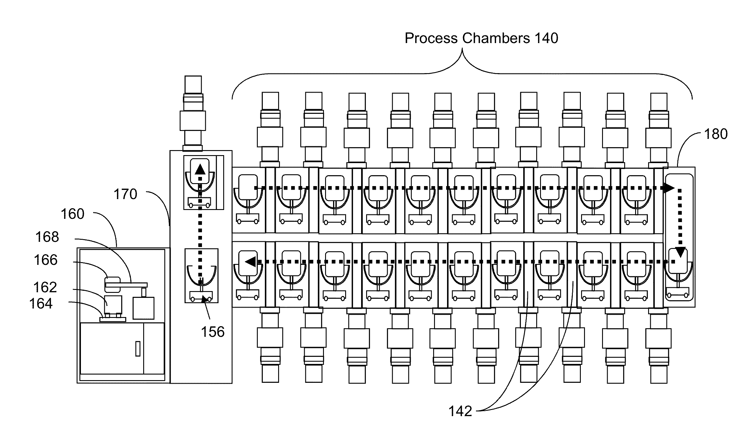
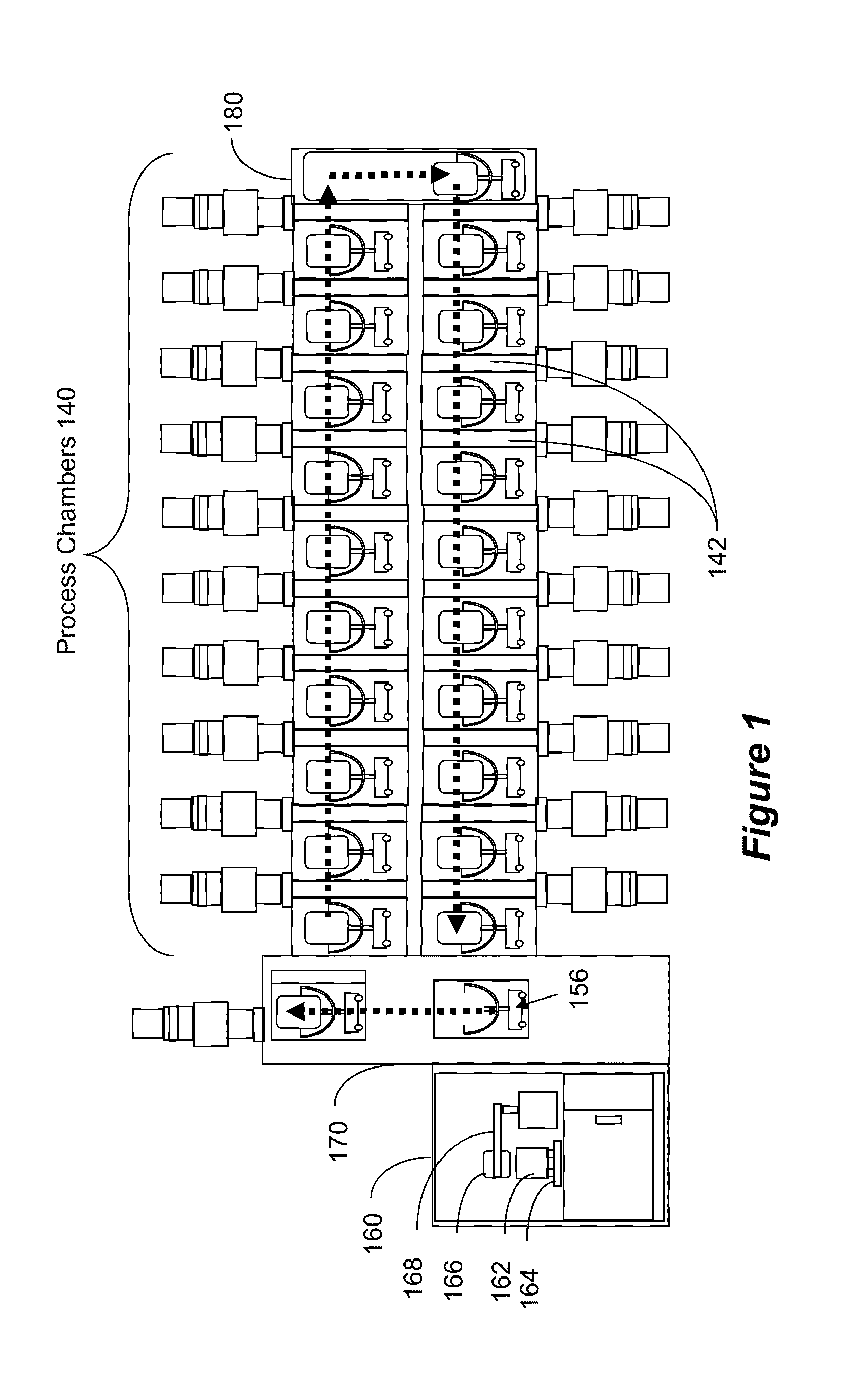
[0035]A process to produce a viable magnetic recording disc has been developed, using the described magnetron. The process preceding the carbon overcoat step is generalized to include a series of front end cleaning operations and possible mechanical texturing in preparation for multilayer deposition, which is not particularly relevant to the method of the invention. Furthermore, it is assumed that the preceding steps occurring prior to carbon deposition include some combination of magnetic and non-magnetic materials (predominantly metals) and that the disc temperature heading into the carbon deposition station is in the range of 300-500 K. A ta-C carbon deposition then ensues with the cathode pairs (one about each side of the disc) such that each has a target pair separated by 50 mm, with peripheral magnets having north magnetic pole pointing towards the target and a center magnet having a south magnetic pole pointing towards the target. The target on the opposite side has the oppos...


PUM

PropertyMeasurementUnit
Poweraaaaaaaaaa
Transport propertiesaaaaaaaaaa
Vacuumaaaaaaaaaa

Abstract

A deposition system is provided, where conductive targets of similar composition are situated opposing each other. The system is aligned parallel with a substrate, which is located outside the resulting plasma that is largely confined between the two cathodes. A “plasma cage” is formed wherein the carbon atoms collide with accelerating electrons and get highly ionized. The electrons are trapped inside the plasma cage, while the ionized carbon atoms are deposited on the surface of the substrate. Since the electrons are confined to the plasma cage, no substrate damage or heating occurs. Additionally, argon atoms, which are used to ignite and sustain the plasma and to sputter carbon atoms from the target, do not reach the substrate, so as to avoid damaging the substrate.

Description

CROSS-REFERENCE TO RELATED APPLICATIONS[0001]This application is a continuation-in-part of and claims priority benefit from U.S. application Ser. No. 13 / 094,779, filed Apr. 26, 2011, which claims priority from U.S. Provisional Application No. 61 / 424,550, filed on Dec. 17, 2010, the entirety of both which is incorporated herein by reference.BACKGROUND[0002]1. Field[0003]This application relates to the art of forming thin films, such as by physical vapor deposition (PVD). More specifically, this application relates to forming thin film, such as diamond-like coating (DLC) on substrates, such as magnetic disks used in hard drives.[0004]2. Related Art[0005]Hard drive disks are fabricated by forming various thin-film layers over a round substrate. Some of these layers include magnetic materials that is used as the memory medium, and some of these layers are formed as protection. Finally, a lubricant layer is deposited on the surface of the disk to enable smooth flying of the magnetic read...

Claims


Application Information

Patent Timeline
IPC IPC(8): C23C14/35
CPCC23C14/35C23C14/352H01J37/3405H01J37/3417H01J37/345
Inventor HARKNESS, IV, SAMUEL D.BLUCK, TERRYRUSSAK, MICHAEL A.TRAN, QUANG N.BROWN, DAVID WARD
Owner INTEVAC
Why Eureka
Try Eureka