
Solar selective absorber based on double nitride composite material and process for its preparation

a composite material and selective technology, applied in solar heat devices, solar ion implantation coatings, lighting and heating apparatuses, etc., can solve the problems of low reliability in terms of physical and chemical characteristics of the material itself, low emissivity, and low heat storage to the outside environment. , to achieve the effect of excellent performance, low emissivity and high absorban

Active Publication Date: 2014-05-15
ENTE PER LE NUOVE TECH LENERGIA E LAMBIENTE ENEA
View PDF1 Cites 9 Cited by
  • Summary
  • Abstract
  • Description
  • Claims
  • Application Information

AI Technical Summary

Benefits of technology

The present invention is a coating material that is suitable for use in a thermoelectric solar installation operating at high temperatures. The coating has excellent photo-thermal properties with high absorption and low emissivity over a wide range of temperatures. The coating is prepared using high-deposition rate processes, such as reactive and non-reactive sputtering, which enhance productivity and decrease costs. The invention meets the need for a novel material with these properties and is suitable for use in a variety of solar concentration systems.

Problems solved by technology

In particular, it should absorb the greatest possible amount of solar radiation concentrated thereon and, at the same time, it should lose to the outside environment the least possible amount of heat stored.
However, cermets currently marketed and utilized as absorbers for receiver elements in solar installations have, as will be better illustrated hereinafter, limitations as regards their chemical-structural stability when subjected to high temperatures (temperatures comprised between 450° C. and 550° C.) and reproducibility of the material, with the consequence of a low reliability in terms of physical and chemical features of the material itself.
Such problems are typical of marketed cermets, and are partly attributable to the materials and processes used for producing them.

Method used


Image

  • Solar selective absorber based on double nitride composite material and process for its preparation
  • Solar selective absorber based on double nitride composite material and process for its preparation
  • Solar selective absorber based on double nitride composite material and process for its preparation

Examples


example 1

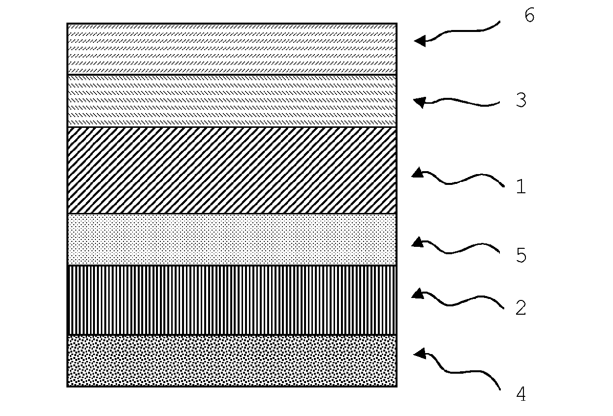
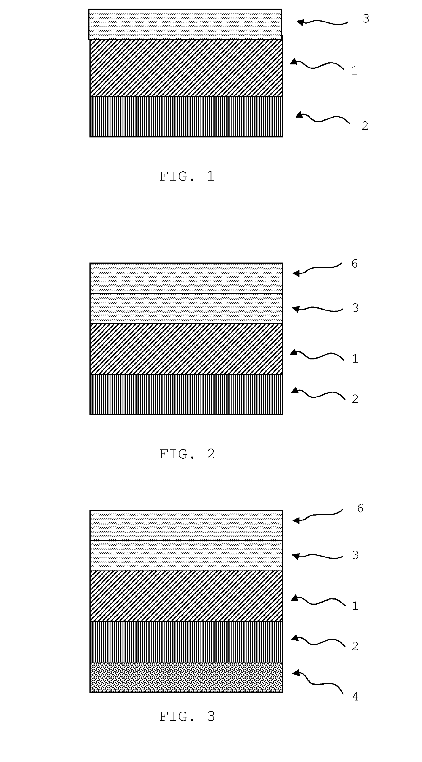
[0190]the material illustrated in FIG. 1 was made.

LayerMaterialThickness1—cermettungsten nitride-aluminumabout 0.10 μmnitride2—reflecting metallic(α-phase) tungstenabout 0.13 μm3—antireflectionaluminum nitrideabout 0.08 μm

example 2

[0191]the material illustrated in FIG. 2 was made.

LayerMaterialThickness1—cermettungsten nitride-aluminumabout 0.10 μmnitride2—reflecting metallic(α-phase) tungstenabout 0.13 μm3—antireflectionaluminum nitrideabout 0.08 μm6—2nd antireflection layerSiO2about 0.08 μm

example 3

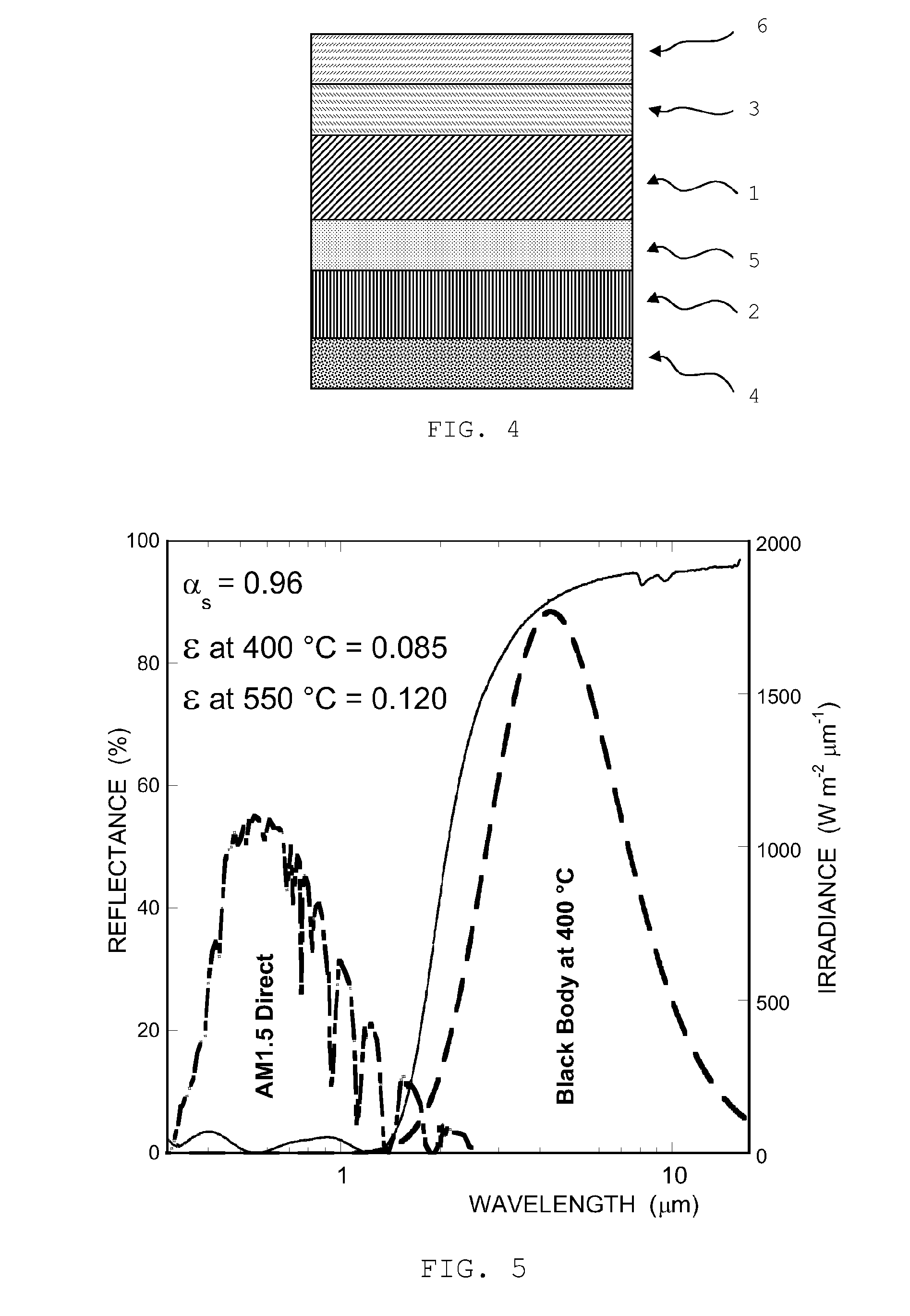
[0192]the material illustrated in FIG. 3 was made.

LayerMaterialThickness1—cermettungsten nitride-aluminumabout 0.10 μmnitride2—reflecting metallic(α-phase) tungstenabout 0.13 μm3—antireflectionaluminum nitrideabout 0.08 μm6—2nd antireflection layerSiO2about 0.08 μm4—adhesive adaptiveAl2O3about 0.06 μm


PUM

PropertyMeasurementUnit
temperatureaaaaaaaaaa
operating temperaturesaaaaaaaaaa
emissivity εhaaaaaaaaaa

Abstract

A thin-film spectrally selective coating for receiver tube of vacuumed type for use in thermodynamic solar installations and operating both at medium temperature (up to 400° C.) and at high temperature (up to 550° C.), coating where the optically absorbing layer is a multilayer of cermet material of type: WyN—AlNx or MoyN—AlNx, material prepared with reactive co-sputtering technique from an Al target and a W or Mo target, process conducted under a transition regimen, under PFM (Plasma Emission Monitoring) or CVM (Cathode Voltage Monitoring) monitoring for the sole Al target, with inletting near the Al target of a N2 amount adequate for obtainment of a high-transparency, high growth rate sub-stoichiometric ceramic AlN and with inletting near the W or Mo target of a N2 amount adequate for obtainment of the sole W2N or Mo2N phase, phase very stable at high temperature, such as to make the cermet material as close as possible to the formulation W2N—AlNx or Mo2N—AlNx (with x comprised between 0.90 and 1.00, preferably 0.95) and, therefore, cermet material employable at least up to the temperature of 550° C.

Description

FIELD OF THE INVENTION[0001]The present invention relates to:[0002]an optically selective double-nitride composite material consisting of a ceramic matrix and a component having a metallic behavior nanodispersed therein;[0003]a spectrally selective multilayer coating material for use in solar to installations, mainly of thermodynamic type and preferably of the type having linear parabolic mirrors, apt to operate at high temperature;[0004]a process of preparation of the composite material and of the multilayer material; and[0005]a receiver element for thermodynamic solar installations, made with said coating material and a process of coating such receiver element.BACKGROUND OF THE INVENTION[0006]In the field of thermodynamic solar installations, with reference e.g. to parabolic mirror technology, the receiver element, which in this case is a receiver tube positioned along the focal line of the mirrors, has to act as an absorber. In particular, it should absorb the greatest possible a...

Claims


Application Information

Patent Timeline
Patent Type & Authority Applications(United States)
IPC IPC(8): F24J2/48C23C14/34G02B5/08C23C14/14G02B1/10F24J2/46C23C14/06
CPCF24J2/485C23C14/0617C23C14/0652G02B5/085C23C14/34F24J2/4652G02B1/10C23C14/14C23C14/0042C23C14/0641C23C14/3464C04B35/581C04B35/584C04B2235/3886C04B2235/75C04B2235/79C04B2235/80Y02E10/40F24S70/30F24S70/225C04B35/62222C23C14/022
Inventor ANTONAIA, ALESSANDROESPOSITO, SALVATOREADDONIZIO, MARIA LUISAGUGLIELMO, ANTONIO
Owner ENTE PER LE NUOVE TECH LENERGIA E LAMBIENTE ENEA
Learn More