
Composition for colloidal crystal

a colloidal crystal and composition technology, applied in the field of colloidal crystal composition, can solve the problems of difficult colloidal crystals, high cost, and high cost, and achieve the effect of simple process and efficient manufacturing

Inactive Publication Date: 2013-07-04
NOF CORP
View PDF4 Cites 25 Cited by
  • Summary
  • Abstract
  • Description
  • Claims
  • Application Information

AI Technical Summary

Benefits of technology

The present inventors found that using a composition with core-shell particles and a binder monomer with a high refractive index can improve the optical properties of a colloidal crystal cured film. The shell contains a linear polymer with a higher refractive index than the core, which results in improved optical properties.

Problems solved by technology

The hard colloidal crystals are composed of particles accumulated only by contact and therefore have very low mechanical strength, and are broken by the action of a slight external force.
However, this requires complicated procedures with many steps.
Furthermore, it is difficult to completely fill the voids between particles with the binder, and disordered voids often remain.
The residual disordered voids cause light scattering and consequently cloudiness in the resulting colloidal crystals.
The hard colloidal crystals tend to have an infinite number of cracks in its coating film during the drying process.
This is because, with decreasing interparticle distance during the drying process, uneven shrinkage results in the breakage of part of the crystals, thus causing cracks.
These cracks have various sizes and may be large enough for visual observation or may be microcracks of several micrometers, which are difficult to visually observe.
An infinite number of these cracks also scatter light and cause cloudiness in the resulting colloidal crystals.
It is therefore difficult to completely fill the voids with the resin.
Furthermore, it is difficult to prevent all cracks only with the polymer of the shell.
Thus, there are problems that the immobilization of colloidal crystals requires complicated procedures or substrates, and residual voids or cracks cause cloudiness.
However, a regular arrangement of particles is likely to be broken during the polymerization of the monomer.
Thus, there is a problem that the optical properties cannot sufficiently be maintained through the curing.
Thus, the regular arrangement of particles is difficult to maintain during the immobilization of the colloidal crystals.
Thus, colloidal crystals immobilized as a gel containing a water-soluble solvent or an organic solvent have low mechanical strength and are therefore difficult to put to practical use in optical functional materials.
Furthermore, the evaporation of the solvent may disorder the regular arrangement of particles or change the interparticle distance.
This changes the reflection wavelength, resulting in poor stability.
However, the colloidal crystal cured film disclosed in JP2010-18760A suffers from still insufficient curing and has a high haze because of slight residual cloudiness.
However, this also increases the haze.

Method used


Image

  • Composition for colloidal crystal
  • Composition for colloidal crystal
  • Composition for colloidal crystal

Examples


example 1-1

Synthesis of Core

(Core D)

[0138]A core was synthesized by two-stage seed emulsion polymerization. At the first stage, a 500-mL four-neck flask equipped with a condenser tube, a thermometer, an agitator, and a nitrogen inlet was charged with 0.146 g of a reactive emulsifier sodium styrenesulfonate (NaSS) and 350 g of ion-exchanged water. 13.72 g of a monomer methyl methacrylate (MMA) and 0.730 g of a cross-linking monomer ethylene glycol dimethacrylate (EGDM) were added to the flask, were mixed in a nitrogen stream, and were heated to 65° C. 0.0292 g of a polymerization initiator potassium persulfate (KPS) was then added to the reaction solution. After polymerization reaction at 65° C. for 5 hours, the reaction solution was cooled to room temperature.

[0139]At the second stage, 0.219 g of an emulsifier sodium dodecylbenzenesulfonate (DBS) was added to the reaction solution and was mixed at room temperature in a nitrogen stream. 0.730 g of a m / p mixture of 2-(4′-hydroxy-2′,2′,6′,6′-tetr...

examples 1-2 to 5-3

and Comparative Examples 1 to 5

Cores E to O

[0144]In the same manner as the core D, the cores E to 0 were synthesized using the amount of usage listed in Table 1. Table 1 shows the results.

[0145]The symbols in the following Tables 1 to 9 are as follows:

[0146]EMA: ethyl methacrylate

[0147]tBA: tert-butyl acrylate

[0148]tBMA: tert-butyl methacrylate

[0149]BDMA: 1,4-butanediol dimethacrylate

[0150]TFEMA: 2,2,2-trifluoroethyl methacrylate

[0151]St: styrene

[0152]BzMA: benzyl methacrylate

[0153]DVB: divinylbenzene (purity 55%, containing ethylvinylbenzene 45%)

[0154]HS-10: Aqualon HS-10 [manufactured by Dai-ichi Kogyo Seiyaku Co., Ltd.]

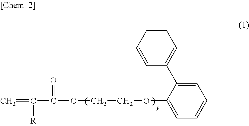
[0155]BPEA: 2-phenylphenoxyethyl acrylate (NK ester A-LEN-10 [manufactured by Shin Nakamura Chemical Co., Ltd.]) (see the following chemical formula)

[0156]BPA: 2-phenylphenyl acrylate (ARONIX TO-2344 [manufactured by Toagosei Co., Ltd.]) (see the following chemical formula)

[0157]BPM: 2-phenylphenyl methacrylate (see the following chemical formula)

[0158]LA: lauryl a...


PUM

PropertyMeasurementUnit
Fractionaaaaaaaaaa
Fractionaaaaaaaaaa
Percent by massaaaaaaaaaa

Abstract

A composition for colloidal crystals including core-shell particles and a monomer having a particular structure. The core-shell particles constitute 25% to 65% by weight of the composition, and the monomer constitutes 35% to 75% by weight of the composition. The core has an average particle size from 50 to 900 nm. Each particle includes a core and a shell. The shell is formed of a linear polymer composed of at least one of styrene and a monomer having a particular structure. One end of the linear polymer is covalently bonded to the core. The refractive index of the core (n(core)) satisfies the following formulae: wherein R1 denotes a hydrogen atom or a methyl group, and y is 0 or 1, n(shell)−n(core)≧0.07, n(shell) denoting the refractive index of the shell, and n(B)−n(core)≧0.07, n(B) denoting the refractive index of the monomer (B1) after curing.

Description

PRIORITY CLAIM[0001]The present application is a National Phase entry of PCT Application No. PCT / JP2011 / 062594, filed Jun. 1, 2011, which claims priority from Japanese Patent Application No. 2010-144494, filed Jun. 25, 2010, the disclosures of which are hereby incorporated by reference herein in their entirety.BACKGROUND OF THE INVENTION[0002]The present disclosure relates to a composition with which a coloring material for presenting a structural color and colloidal crystals usable as an optical element can be produced, a colloidal crystal film formed of the composition, and a method for manufacturing the colloidal crystal cured film. A composition for colloidal crystals and a colloidal crystal cured film according to the present disclosure are useful for applications in the optical technical field, such as optical elements and optical functional materials.[0003]An accumulation of monodisperse particles three-dimensionally regularly arranged is referred to as colloidal crystals. Th...

Claims


Application Information

Patent Timeline
IPC IPC(8): C09D139/04
CPCC08F2/44C08F285/00G02B1/02Y10T428/2998C08F2220/306C08F2222/102Y10T428/254C09D139/04B32B5/14B32B7/02B05D2401/10C08F220/10C08F220/306C08F222/1025
Inventor HAYASHI, MASAKITAKAMURA, MASUMI
Owner NOF CORP
Learn More