Microfluidic system with metered fluid loading system for microfluidic device
a microfluidic and fluid loading technology, applied in microstructural devices, microstructured devices, microstructured technology, etc., can solve the problems of energetically unfavourable filling of aqueous fluids into such devices, and achieve the effects of preventing device overload, improving assay accuracy, and convenient fabrication
- Summary
- Abstract
- Description
- Claims
- Application Information
AI Technical Summary
Benefits of technology
Problems solved by technology
Method used
Image


Examples
first embodiment
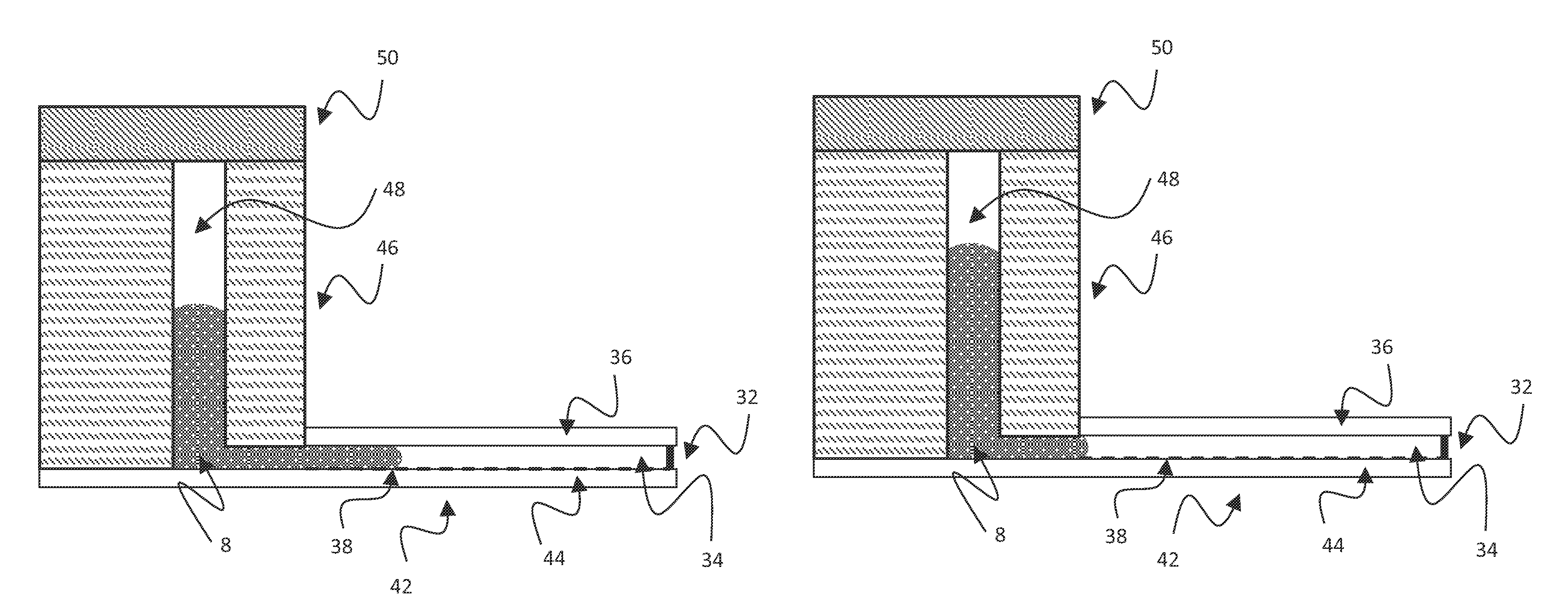
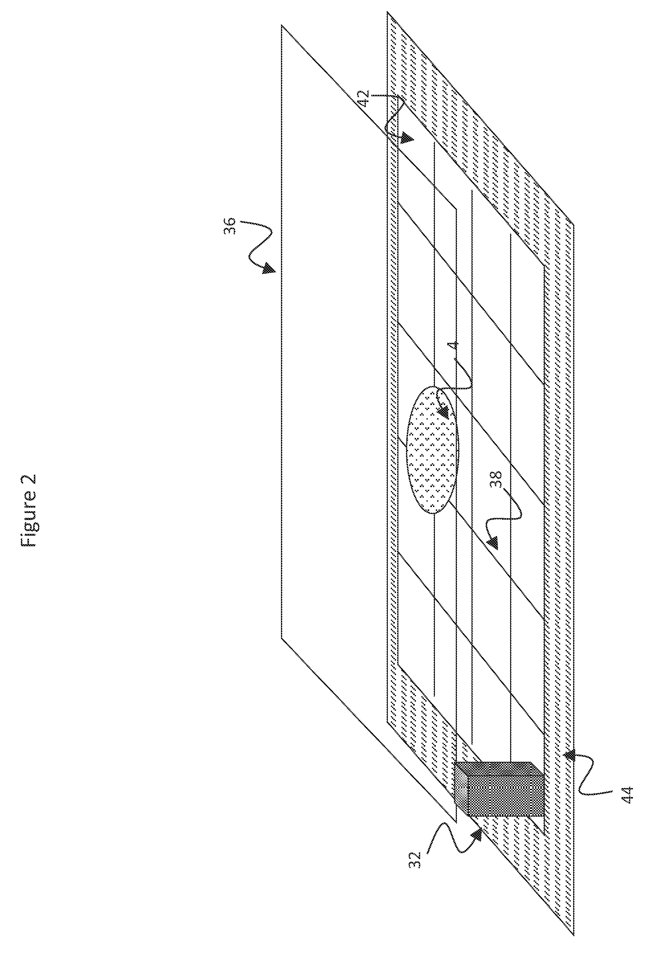
[0100]FIGS. 3a-3c illustrate the invention. In addition to the EWOD components (insulator layers 20 and hydrophobic layers 26 are not shown for clarity) there is provided a metered fluid loading system for inputting fluids, and namely a discrete metered volume of fluid, into the EWOD device. The system preferably is formed integrally with the EWOD device, for example formed on the same lower substrate 44. The entire assembly may be fabricated at low cost, for example by injection moulding. The metered fluid loading system includes a reservoir 46 containing an input channel 48. Such a reservoir 46 is illustrated in projection view in FIG. 4. The input channel 48 is configured to couple the fluid from the reservoir 46 into a gap between the top substrate 36 and the lower substrate 44 of the EWOD device. The system further includes a fluid input mechanism, generally designated 50, which cooperates with the reservoir 46 and is in airtight contact with it. The fluid input mechanism 50 op...
second embodiment
[0104]FIGS. 5a-5b illustrate the invention providing a specific implementation of the fluid input mechanism. The fluid input mechanism includes a bistable actuator 52 which may readily adopt either a first or second shape. For example, the first shape (first bistable state) may be a convex section of a sphere or ellipsoid (as shown in FIG. 5a) whilst the second shape (second bistable state) may be a concave section of a sphere or ellipsoid (as shown in FIG. 5b). Such a bistable actuator 52 may be made, for example, of a suitable semi-flexible material such that on application of an external force it will deform from the first shape to the second shape. Suitable materials include polystyrene copolymers such as High Impact Polystyrene. This force may be applied for example by an external rigid elongate element (not shown) pressed momentarily against the actuator 52. FIG. 5a illustrates the bistable actuator 52 in its first shape. FIG. 5b illustrates the bistable actuator 52 in its sec...
third embodiment
[0105]FIGS. 6a-6b illustrate the invention providing a further implementation of the fluid input mechanism. The fluid input mechanism includes a deformable membrane actuator 54 which is made of a suitable material capable of being deformed on application of an external force. This force may be applied for example by an external rigid elongate element (not shown) pressed against the actuator 54. In some applications it is useful if this deformation is reversible on removal of the force. Suitable materials from which the actuator 54 may be made include elastomers such as silicone rubbers, natural rubber, nitrile rubbers, or fluoroelastomers such as copolymers of hexafluoropropylene (HFP) and vinylidene fluoride (VDF or VF2). The actuator 54 is coupled to a reservoir 56 which differs from the reservoir of previous embodiments in that the top of the input channel 48 is structured as to form a limiter which limits the extent of deformation of the actuator 54. In the embodiment of FIGS. 6...
PUM
 Abstract
Description
Claims
Application Information
 - R&D
- Intellectual Property
- Life Sciences
- Materials
- Tech Scout
- Unparalleled Data Quality
- Higher Quality Content
- 60% Fewer Hallucinations
Browse by: Latest US Patents, China's latest patents, Technical Efficacy Thesaurus, Application Domain, Technology Topic, Popular Technical Reports.
© 2025 PatSnap. All rights reserved.Legal|Privacy policy|Modern Slavery Act Transparency Statement|Sitemap|About US| Contact US: help@patsnap.com