
Operating method for hydrogen/natural gas blends within a reheat gas turbine

a gas turbine and hydrogen/natural gas technology, applied in the direction of machines/engines, mechanical equipment, engine starters, etc., can solve the problems of reducing generating capacity, inability to increase production at peak load, and excess electricity, so as to improve lbo, reduce nox and co emissions, and increase stability. range

Inactive Publication Date: 2013-04-18
ANSALDO ENERGIA IP UK LTD
View PDF13 Cites 11 Cited by
  • Summary
  • Abstract
  • Description
  • Claims
  • Application Information

AI Technical Summary

Benefits of technology

The patent text describes a gas turbine system that can use different blends of natural gas and hydrogen depending on availability and operating conditions. By adding varying amounts of hydrogen to the fuel, the system can achieve better flame position and reduced emissions of NOx and CO. In one case, up to 20% hydrogen can be added to reduce CO emissions at partial load conditions. In another case, adding 30% or more hydrogen can improve LBO (lower boundary oxidation).

Problems solved by technology

This leads to potentially excess electricity at off peak times and the potential for having to reduce generating capacity and the inability to increase production at peak load.
It is consequently probable that insufficient hydrogen would be available for sustained base load operation.
It should also be noted that many alternative energy sources provide inconsistent power outputs (e.g. wind or wave generators) that would cause the available quantity to vary with time.
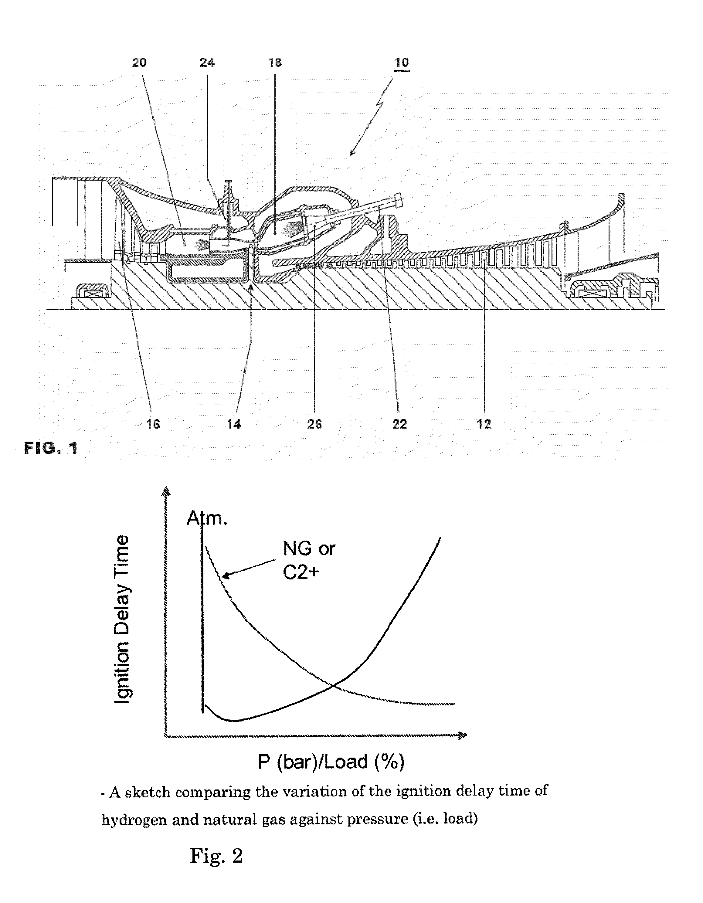
As the combustor inlet temperature is greater than the auto-ignition temperature of the fuel, combustion occurs after a characteristic delay time.
The auto-ignition delay time, the stabilizing factor in the reheat burner is also influenced by these parameters but as the axial location of the flame can alter within the combustor with limited impact on performance the potential exists to design a reheat combustion system that can tolerate a range of fuel compositions.
This is only achievable by reducing the flame temperature in the first combustion system; therefore the extent to which this can be achieved is limited by the flame stability in this burner.
This means that the use hydrogen poses particular challenges during starting the engine.

Method used


Image

  • Operating method for hydrogen/natural gas blends within a reheat gas turbine
  • Operating method for hydrogen/natural gas blends within a reheat gas turbine
  • Operating method for hydrogen/natural gas blends within a reheat gas turbine

Examples


Embodiment Construction

[0033]The disclosure deals with current and future capability to burn hydrogen enriched natural gas as a means of utilizing excess renewable generating capacity during off-peak periods. It relates to an operating method for the operation of an industrial gas turbine with a hydrogen enriched natural gas fuel and / or a diluted hydrogen fuel.

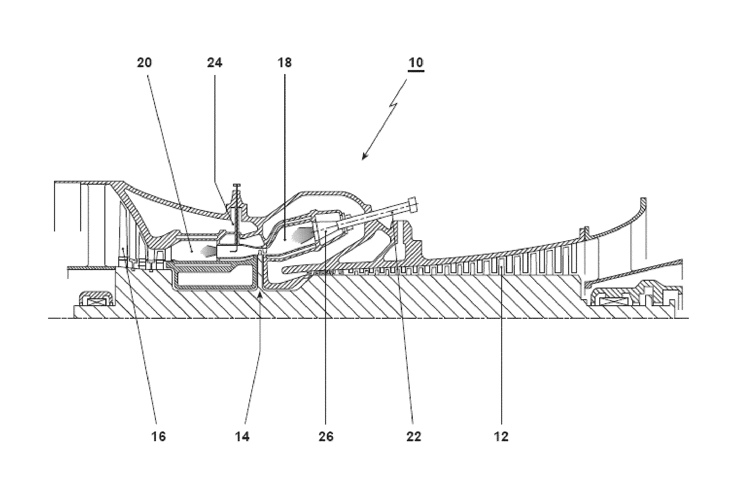
[0034]FIG. 1 shows a reheat gas turbine 10 with a compressor 12, high pressure and low pressure output turbine blade sections or stages 14, 16, and first and second annular combustors 18, 20. Fuel is injected into the combustors 18, 20 with fuel lances 22, 24, for the respective chambers 18, 20. The fuel is preferably a controlled mix of natural gas and hydrogen. As shown schematically in FIG. 11, the fuel is blended in fuel blending systems 30, 30′, preferably mixing chambers, associated with each turbine stage in which varying amounts of natural gas and hydrogen are mixed depending on operating conditions and / or the availability of hydrogen requir...


PUM


Abstract

A gas turbine is operated using a varying blend of a first fuel, preferably natural gas, and a second fuel that is hydrogen. The hydrogen concentration is varied depending on operating conditions in order to reduce emissions of CO and NOx, and / or to mitigate LBO. The fuel mixture is varied using a controller based on a combination of factors in a modular operation concept to address different issues according to relevant load limitations. A method of operating a gas turbine according to this modular operational concept is also provided.

Description

INCORPORATION BY REFERENCE[0001]The following documents are incorporated herein by reference as if fully set forth: U.S. Provisional Application No. 61 / 546,321, filed Oct. 12, 2011.FIELD OF INVENTION[0002]The present invention relates to the field of combustion technology for gas turbines.BACKGROUND OF THE INVENTION[0003]The investigation of hydrogen rich fuels has been ongoing for some time due to its significant environmental benefits. In particular two specific routes for hydrogen combustion have been widely investigated, these are:[0004]1. Combustion of technically pure hydrogen (hydrogen diluted with inerts such that the hydrogen is the dominant volumetric species) in the context of pre-combustion carbon capture.[0005]2. Combustion of synthetic gasses (hydrogen and carbon monoxide blends) derived from the gasification of biological material providing a carbon neutral fuel.[0006]In both of these processes a fuel production facility would be used upstream of the gas turbine which...

Claims


Application Information

Patent Timeline
Patent Type & Authority Applications(United States)
IPC IPC(8): F02C9/40
CPCF01D19/00F02C9/40F02C9/34F02C3/20
Inventor WOOD, JOHN PHILIPPOYYAPAKKAM, MADHAVANCIANI, ANDREASYED, KHAWARLACHAUX, THIERRYGENIN, FRANKLIN MARIEEROGLU, ADNAN
Owner ANSALDO ENERGIA IP UK LTD
Learn More