
Saw wire and method of manufacturing group iii nitride crystal substrate using the same

Inactive Publication Date: 2013-03-14
SUMITOMO ELECTRIC IND LTD
View PDF15 Cites 6 Cited by
  • Summary
  • Abstract
  • Description
  • Claims
  • Application Information

AI Technical Summary

Benefits of technology

This patent is about a method for making nitride crystal substrates with small warping and a high yield. The method involves using a thin saw wire with high tensile strength at break. The technical effect of this method is that it allows for the production of high-quality nitride crystal substrates.

Problems solved by technology

A group III nitride crystal body such as GaN crystal body is generally low in terms of the crystal growth rate and complicated in terms of the manufacture process, and is therefore very expensive.
When a conventional saw wire is used to slice a group III nitride crystal body into thin pieces, a resultant problem is that cracks are likely to open and the yield of group III nitride crystal substrates is low.
In order to reduce this warpage, the tension applied to the saw wire when the group III nitride crystal body is sliced (this tension is hereinafter referred to as stretch tension) should be higher than 8 N, preferably higher than 10 N. An increased tension (stretch tension) applied to the saw wire results in a problem of an increased probability of wire breakage during a slicing process.
It has thus been difficult to slice a group III nitride crystal body with safety and with a high yield.

Method used


Image

  • Saw wire and method of manufacturing group iii nitride crystal substrate using the same
  • Saw wire and method of manufacturing group iii nitride crystal substrate using the same
  • Saw wire and method of manufacturing group iii nitride crystal substrate using the same

Examples


first embodiment

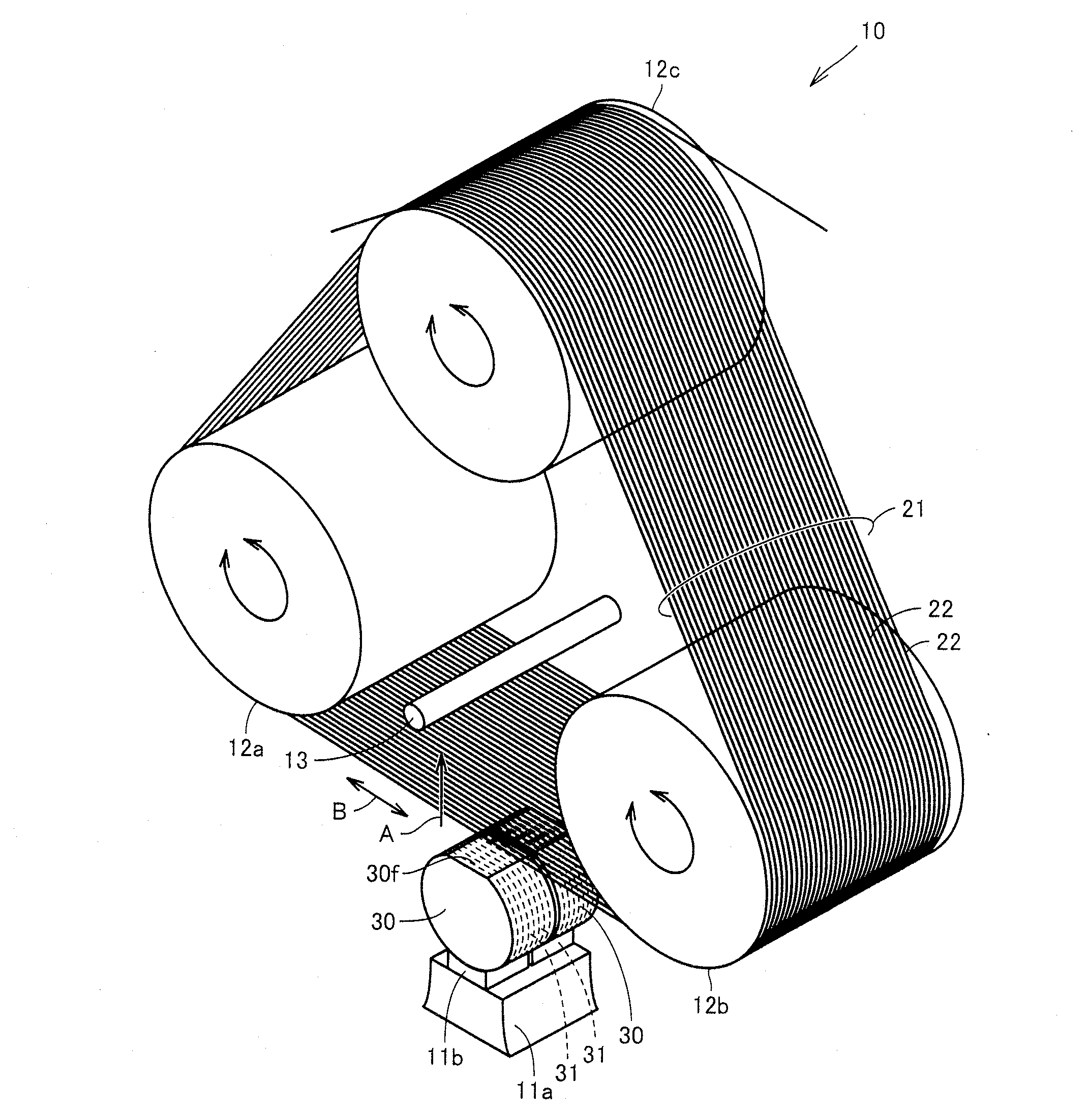
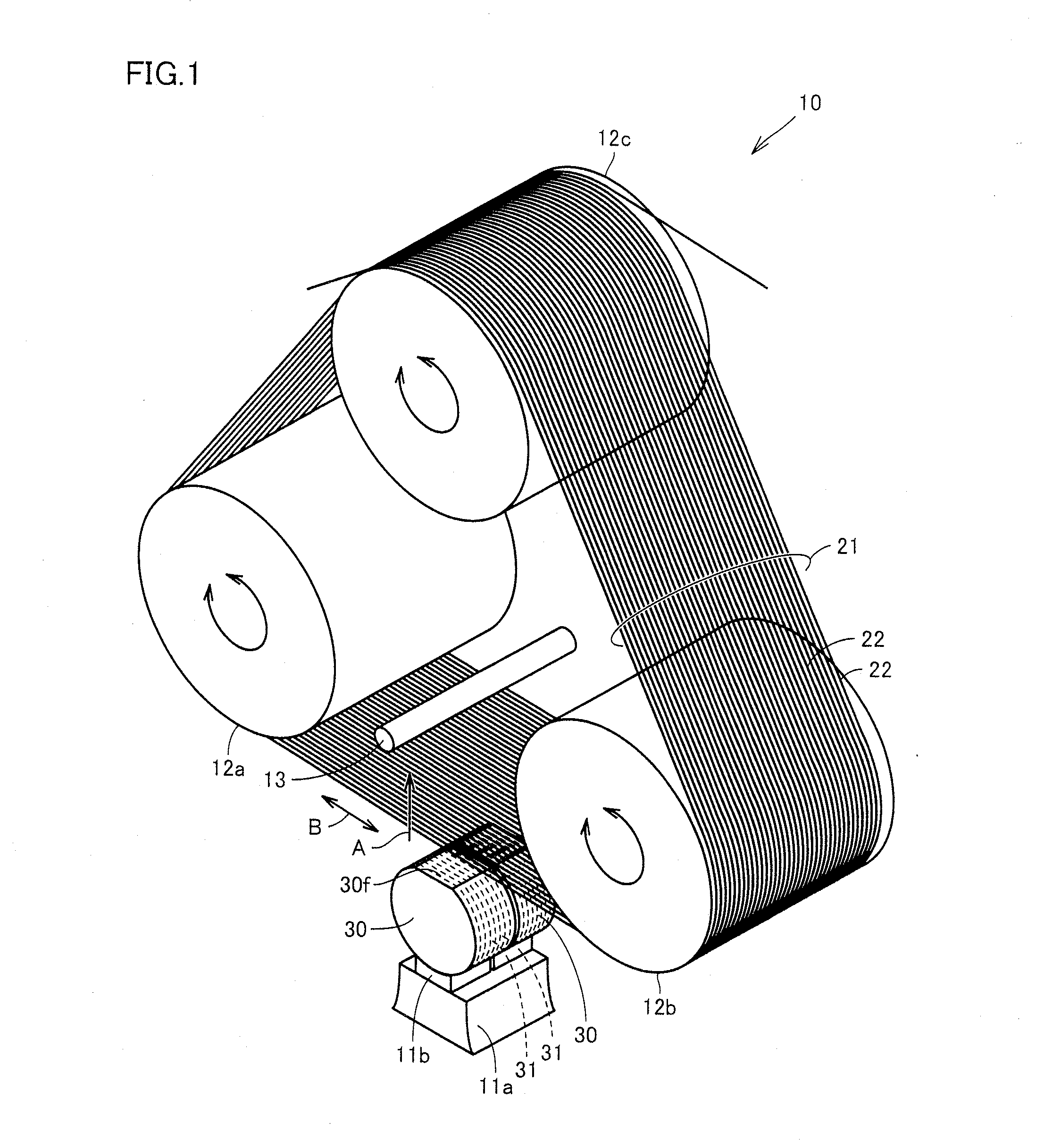
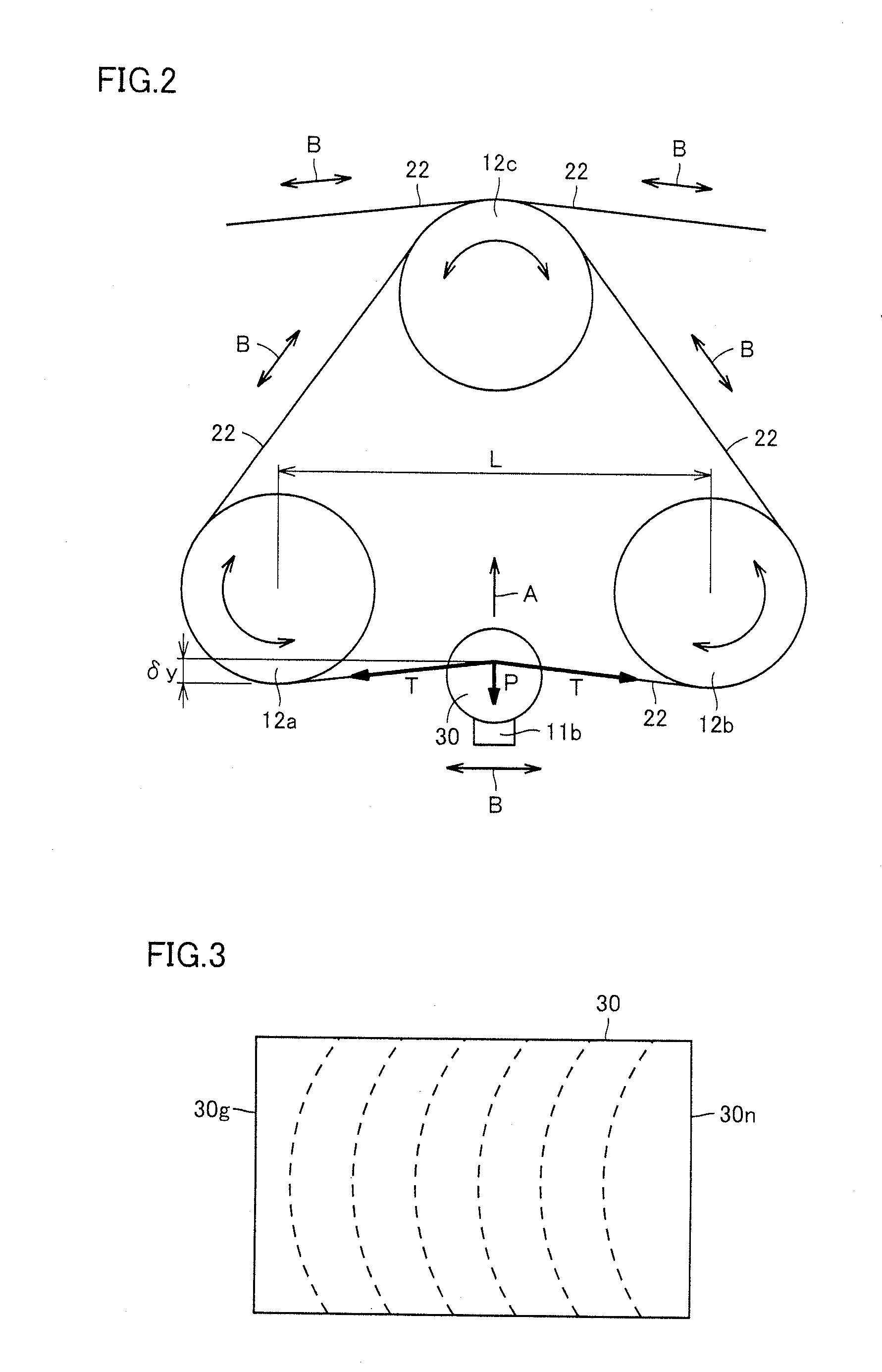
[0021]Referring to FIGS. 1 and 2, a saw wire 22 in an embodiment of the present invention includes a steel wire having a carbon concentration of not less than 0.90 mass % and not more than 0.95 mass %, a silicon concentration of not less than 0.12 mass % and not more than 0.32 mass %, a manganese concentration of not less than 0.40 mass % and not more than 0.90 mass %, a phosphorus concentration of not more than 0.025 mass %, a sulfur concentration of not more than 0.025 mass %, and a copper concentration of not more than 0.20 mass %. Saw wire 22 of the present embodiment includes the above-described steel wire, and therefore, the saw wire has a high tensile strength at break and a high tension can be applied thereto without breaking the wire even if the wire is a thin wire of a small diameter.

[0022]The steel wire included in saw wire 22 of the present embodiment has the following chemical components in order to have a high tensile strength at break. Carbon is an element that is eff...

second embodiment

[0028]Referring to FIGS. 1 to 4, a method of manufacturing a group III nitride crystal substrate in another embodiment of the present invention includes the step S1 of preparing a group III nitride crystal body 30 and the step S2 of producing a group III nitride crystal substrate 31 by slicing group III nitride crystal body 30 with saw wire 22 of the first embodiment. This manufacturing method can be used to obtain small-warpage group III nitride crystal substrates with a high yield.

[0029]Step of Preparing Group III Nitride Crystal Body

[0030]Referring to FIGS. 1, 2, and 4, the method of manufacturing a group III nitride crystal substrate of the present embodiment includes the step S1 of preparing group III nitride crystal body 30. In the step S1 of preparing group III nitride crystal body 30, the method of producing group III nitride crystal body 30 is not particularly limited. Vapor phase methods such as HVPE (hydride vapor phase epitaxy) method, MBE (molecular beam epitaxy) method...

example a

[0048]1. Preparation of Group III Nitride Crystal Body

[0049]A GaN crystal body (group III nitride crystal body) grown by the HVPE method and having a front main surface which was a Ga-atom surface ((0001) plane) and a rear main surface which was an N-atom surface ((000-1) plane) was contour-processed through the following procedure. The outer periphery of the GaN crystal body was ground with a diamond abrasive of #800 defined by JIS R6001:1998 so that the diameter was 50.8 mm (2 inches). The front main surface and the rear main surface of the GaN crystal body were ground with a diamond abrasive of #1000 defined by JIS R6001:1998 to shape the GaN crystal body so that the thickness of the GaN crystal body was 20 mm. On the outer periphery of the GaN crystal body, an orientation flat plane which was a (11-20) plane was formed with a diamond abrasive of #800 defined by JIS R6001:1998. Finally, process strain that occurred due to the process was removed by wet etching or dry etching.

[005...


PUM

PropertyMeasurementUnit
Lengthaaaaaaaaaa
Lengthaaaaaaaaaa
Fractionaaaaaaaaaa

Abstract

A method of manufacturing a group III nitride crystal substrate slices a group III nitride crystal body with a saw wire which includes a steel wire having a carbon concentration of 0.90-0.95 mass %, a silicon concentration of 0.12-0.32 mass %, a manganese concentration of 0.40-0.90 mass %, a phosphorus concentration of 0.025 mass % or less, a sulfur concentration of 0.025 mass % or less, and a copper concentration of 0.20 mass % or less, and has a diameter of not less than 0.07 mm and less than 0.16 mm, a tensile strength at break of higher than 4200 N / mm2, and a curl size of 400 mm or more, with a tension of not less than 50% and not more than 65% of the tension at break applied to the saw wire. Thus, group III nitride crystal substrates with small warpage can be manufactured.

Description

BACKGROUND OF THE INVENTION[0001]1. Field of the Invention[0002]The present invention relates to a saw wire suitably used for manufacturing a group III nitride crystal substrate, and a method of manufacturing a group III nitride crystal substrate using the saw wire.[0003]2. Description of the Background Art[0004]Crystal substrates are generally manufactured by slicing a crystal body grown in any of various ways. Regarding how to slice the crystal body, methods of slicing by means of various saw wires have been proposed.[0005]For example, Japanese Patent Laying-Open No. 2000-233356 discloses a method of cutting a workpiece by means of a saw wire including a wire having a tensile strength of 3200 to 4200 N / mm2 and an average hardness of 730 to 900 Hv, with the aim of reducing waviness of a cut plane of the cut workpiece. Japanese Patent Laying-Open No. 2000-328188 discloses a steel wire to be used for a wire saw with the aim of improving properties of a cut plane of a work (workpiece)...

Claims


Application Information

Patent Timeline
IPC IPC(8): B28D5/04
CPCB24B27/0633H01L21/02024B23D61/185
Inventor MATSUMOTO, NAOKIMIKAMI, HIDENORI
Owner SUMITOMO ELECTRIC IND LTD
Learn More