
Transparent film and use thereof

Active Publication Date: 2012-09-13
NITTO DENKO CORP
View PDF1 Cites 3 Cited by
  • Summary
  • Abstract
  • Description
  • Claims
  • Application Information

AI Technical Summary

Benefits of technology

[0012]It is desirable for the transparent film disclosed herein that the peel strength (back-face peel strength) is 2 N / 19 mm or greater as measured by bonding a PSA tape to the back-face layer and peeling the PSA tape from the back-face layer under the conditions of 0.3 m / minute peel speed and 180 degrees peel angle. A transparent film demonstrating such a peel strength is adequate as a support of a surface protection film. That is to say, a surface protection film that has finished serving the role of protection is peeled-off and removed from the adherend (for instance, an optical member such as a polarizer). In so doing, bonding a PSA tape on the back-face of the surface protection film (the surface of the back-face layer) and pulling the PSA tape to separate an extremity of the surface protection film from the adherend allows the workability when removing the surface protection film to be improved and at the same time the burden imposed on the adherend to be attenuated. A surface protection film having the transparent film as a support is suited to the peeling operation that uses a PSA tape, since the back-face layer has an adequate degree of peel strength.
[0013]From the points of view of strength and productivity, or the like, a monolayer structure is desirable as a structure for the back-face layer. In addition, it is desirable that the back-face layer is provided on a first face of the substrate layer. With a constitution in which one, two or more intermediate layers are intercalated between the back-face layer and the substrate layer, sometimes the adhesiveness of the intermediate layer to the substrate layer and the back-face layer is insufficient and the failure initiation load of the back-face layer becomes prone to decreasing. Consequently, adaptation of a constitution in which a back-face layer is provided directly on the substrate layer is advantageous.
[0015]As the lubricant, a reactive lubricant having a functional group capable of bonding a resin component of the back-face layer is preferably adopted. With such a reactive lubricant bonded to a resin component of the back-face layer, movement thereof is suppressed, and moreover the occurrence of excessive resin bleeding or insufficient resin distribution over the back-face layer surface over time is suppressed. Therefore, in use of the above lubricant, a transparent film that satisfies the preferred coefficient of friction Δμ disclosed herein may be easily obtained.
[0016]In another preferred mode, the back-face layer comprises a resin material containing an antistatic component. With a transparent film of such constitution, the back-face layer can be utilized to confer resistance to scratch and antistatic properties. Accordingly, the productivity of the transparent film is better compared to a constitution in which the antistatic layer is provided separately from the back-face layer. In addition, the adhesiveness between the back-face layer and the substrate layer can be raised compared to a constitution in which an antistatic layer is intercalated between the back-face layer and the substrate layer, the development of a transparent film having excellent resistance to scratch is facilitated. Given that providing both satisfactory antistatic properties and high resistance to scratch is straightforward, an electrically conductive polymer can be adopted preferably as the antistatic component.

Problems solved by technology

The reason is that if a scratch mark is present on the surface protection film, whether this scratch is a scratch from the adherend or a scratch from the surface protection film cannot be assessed while the surface protection film is left in a bonded state.
However, since generally resistance to scratch and printability are oppositely related, providing both these capabilities stably at high levels is difficult.

Method used


Image

  • Transparent film and use thereof
  • Transparent film and use thereof

Examples


experimental example 1

Sample A-1

[0077]A urethane acrylate heat curing resin (manufactured by DIC Corporation, product named “ACRYDIC A-814”; hereafter, may also be noted “Resin R1”) and, as a lubricant, alkyl-modified polydimethylsiloxane (modified silicone oil manufactured by Momentive Performance Materials Inc., product named “XF42-A3161”; hereafter, may also be noted “Lubricant L1”) were mixed so that the solid content mass ratio was 100:3, and diluted with a solvent having toluene as the main component to prepare a Coating Solution (composition for back-face layer formation) B-1 with a solid content concentration of 0.8%.

[0078]A 38 μm-thick transparent polyethylene terephthalate (PET) film (hereafter, may also be noted “Substrate F1”) corona-treated on a first face was used as a substrate. To the Coating Solution B-1, 30 parts of a curing agent (a polyisocyanate compound manufactured by DIC Corporation, product named “DN-980”) with respect to 100 parts of solid contents in Resin R1 was mixed, this wa...


PUM

PropertyMeasurementUnit
Temperatureaaaaaaaaaa
Lengthaaaaaaaaaa

Abstract

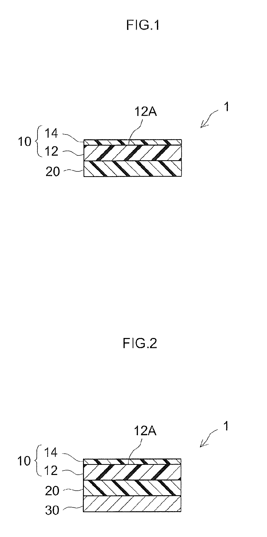
A transparent film, the back-face of which has excellent resistance to scratch and printability, and a surface protection film which has such a transparent film are provided. A transparent film 10 has a substrate layer 12 formed of a transparent resin material, and a back-face layer 14 with a thickness of 1 μm or less provided on a first face 12A thereof. A percent change in coefficient of friction Δμ is less than 10% for the transparent film 10 when the percent change is determined from a coefficient of friction μ50 of the back-face layer after being conserved at 50° C. and 15% RH for three days and a coefficient of friction μ80 of the back-face layer after being conserved at 80° C. and 80% RH for three days, with an absolute value of difference between the two coefficients of friction |μ80−μ50| being divided by the smaller value of the two coefficients of friction.

Description

TECHNICAL FIELD[0001]The present invention relates to a transparent film that is not easily scratch-marked on the back-face and exhibits excellent printing properties and a surface protection film provided with such a film. The present application claims priority based on Japanese Patent Application No. 2009-167207 filed on Jul. 15, 2009, the contents of which are incorporated herein in its entirety by reference.BACKGROUND ART[0002]A surface protection film (also referred to as a surface protection sheet) in general has a constitution in which a pressure-sensitive adhesive (PSA) is provided over a film-shaped support. Such a protection film is bonded matchingly to an adherend through the PSA and thereby used with the purpose of protecting the adherend from scratches and dirt during processing, transport and the like. For instance, a polarizer that is bonded matchingly to a liquid crystal cell in the manufacturing of a liquid crystal display panel is manufactured once in the morpholo...

Claims


Application Information

Patent Timeline
IPC IPC(8): B32B27/00C09J7/29
CPCB32B27/08G02B1/105Y10T428/26C09J2201/606C09J7/0296C09J7/29G02B1/16G02B1/14C09J2301/302C08J5/18B32B2307/21G02B1/10
Inventor HARUTA, HIROMOTOMATSUDA, HIROKAZUINOUEOKUMURA, KAZUHITOKONDO, OSAMUMURAOKA, YOKO
Owner NITTO DENKO CORP
Learn More