Refrigerant compressor and refrigeration cycle apparatus

Active Publication Date: 2012-07-12
TOSHIBA CARRIER CORP
View PDF8 Cites 5 Cited by
  • Summary
  • Abstract
  • Description
  • Claims
  • Application Information

AI Technical Summary

Benefits of technology

[0007]An object of the present invention is to provide a refrigerant compressor that restricts deformation of base members of vanes used in the refrigerant compressor and improves adherence of a film formed on a surface of the base member, and further can restrict wearing of vanes and members that slidably contact with the vanes, and to provide a refrigeration cycle apparatus that uses the refrigerant compressor.

Problems solved by technology

However, there are problems in the adherence between the intermediate layer and the amorphous carbon layer or between the two amorphous carbon layers in a case where two of the amorphous carbon layers are provided.

Method used


Image

  • Refrigerant compressor and refrigeration cycle apparatus
  • Refrigerant compressor and refrigeration cycle apparatus
  • Refrigerant compressor and refrigeration cycle apparatus

Examples


first embodiment

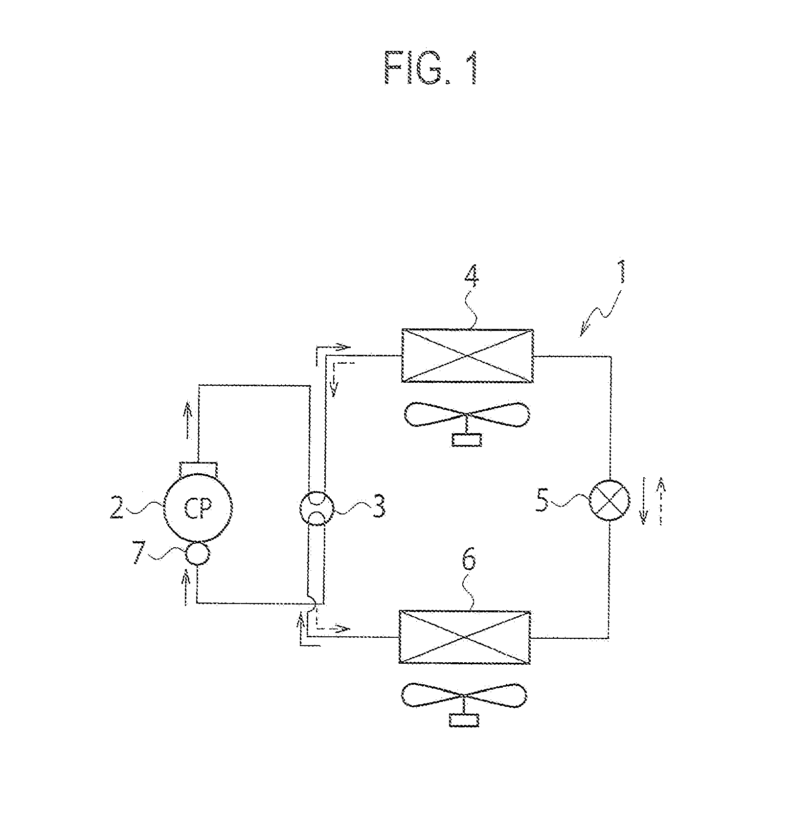
[0018]A first embodiment will be explained with reference to FIGS. 1 to 5. FIG. 1 is a schematic view of a refrigeration cycle apparatus 1 according to the first embodiment.

[0019]A hermetically-sealed rotary-type refrigerant compressor 2, a four-way valve 3, an outdoor heat exchanger 4 that functions as a condenser at a cooling operation and functions as an evaporator at a heating operation, an expansion device 5, an indoor heat exchanger 6 that functions as an evaporator at the cooling operation and functions as a condenser at the heating operation, and an accumulator 7 are connected to configure the refrigeration cycle apparatus 1. Refrigerant circulates above components in the refrigeration cycle apparatus 1.

[0020]In the refrigeration cycle apparatus 1, at its cooling operation, refrigerant discharged from the refrigerant compressor 2 is supplied to the outdoor heat exchanger (condenser) 4 through the four-way valve 3 as shown by solid arrows, and condensed by heat exchanging wit...

second embodiment

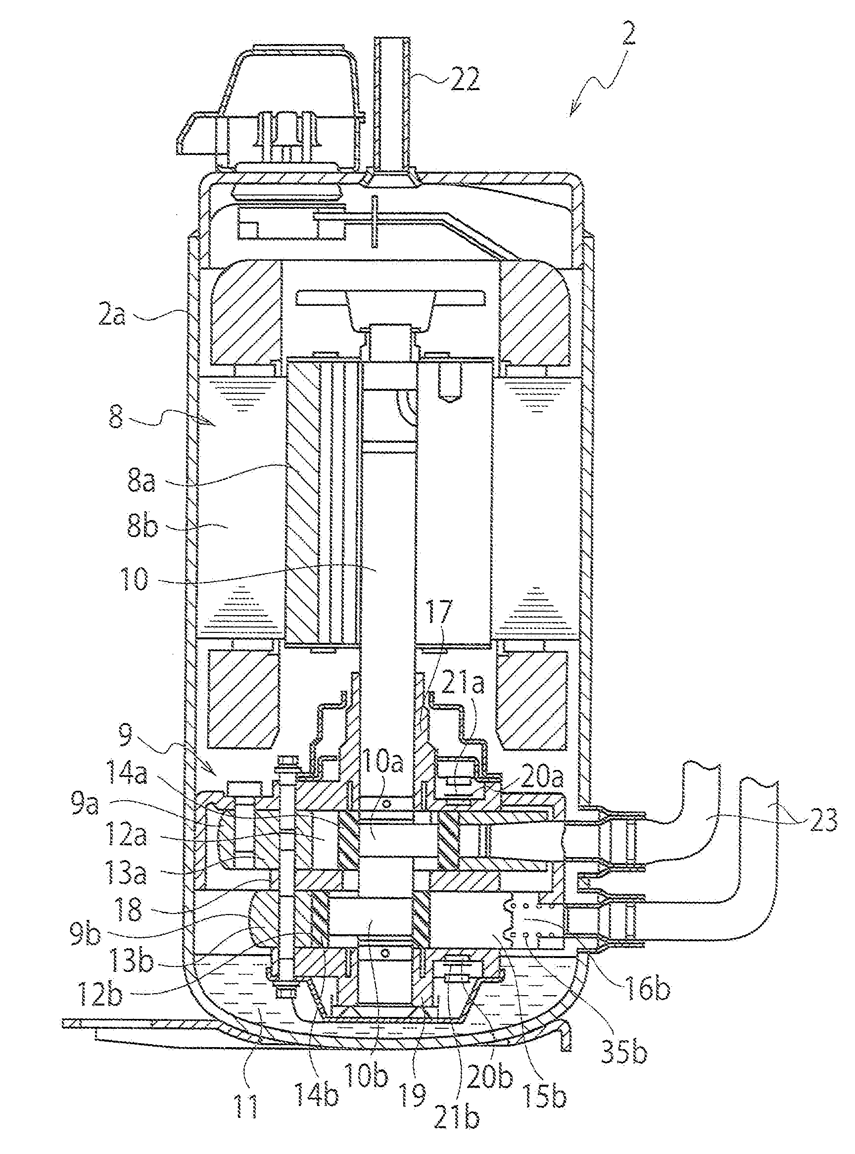
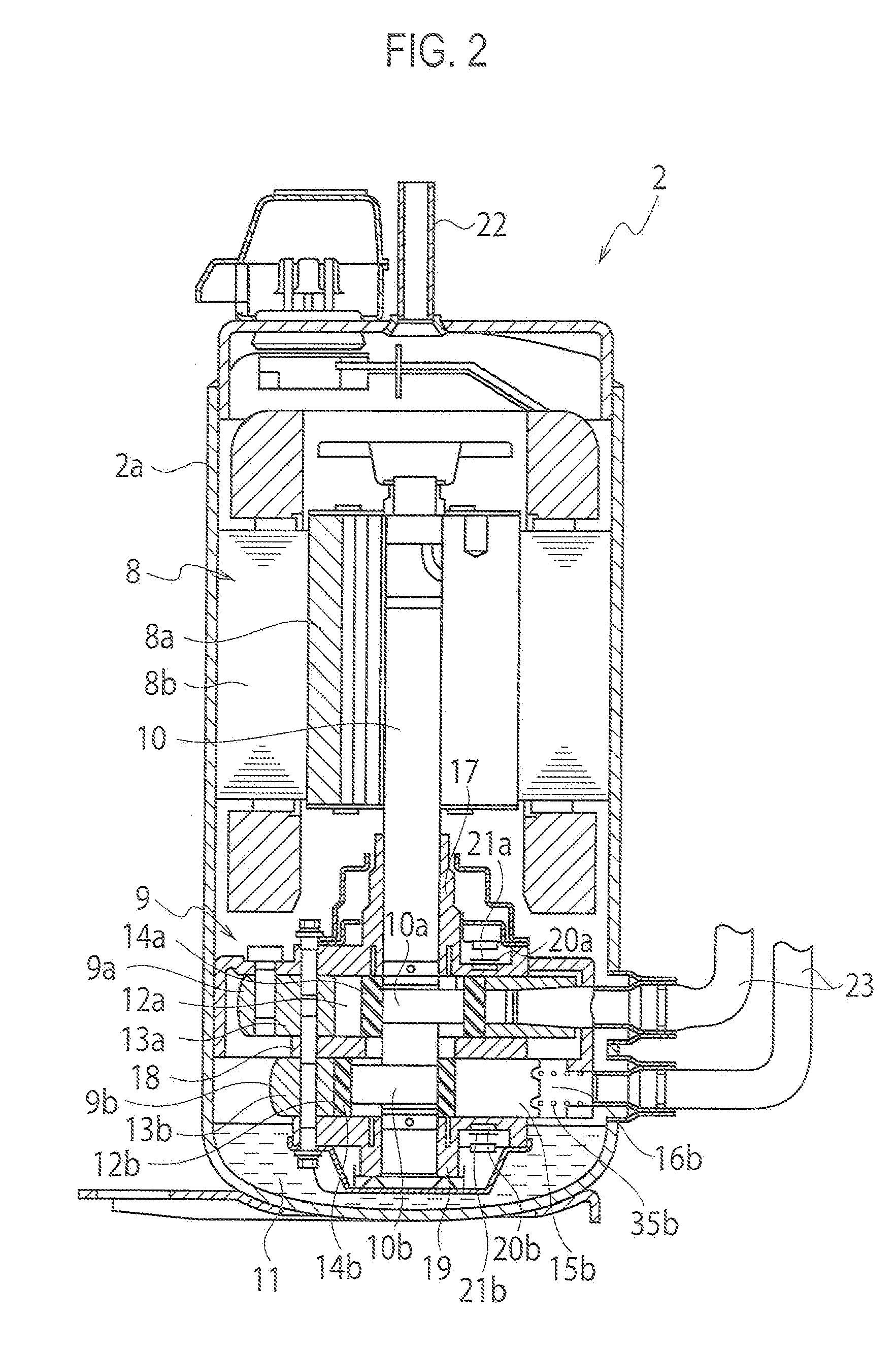
[0055]A second embodiment will be explained with reference to FIGS. 6 and 7. Note that, since fundamental configuration of refrigerant compressors in the second embodiment and in following other embodiments are the same as that of the refrigerant compressor 2 in the first embodiment, their fundamental configuration will be explained with reference to FIGS. 1 to 4.

[0056]In the second embodiment, the cylinders 13a and 13b are made of flake graphite cast iron or made of sintered metal whose surface is treated with a porosity sealing process.

[0057]FIG. 6 is a cross-sectional view of the sintered metal 30 whose surface is treated with a porosity sealing process. In the sintered metal 30, its base member 31 is made of iron, copper and carbon-based sintered alloy, and a ferrosoferric oxide film 32 is formed on the base member 31 with a steam treatment process. In its sintering process, a porous hole(s) 33 is formed on the surface of the base member 31, but the porous hole 33 is filled with...

third embodiment

[0062]A third embodiment will be explained based on a Table 1 shown below. In the present embodiment, the above-explained film 29 composed of the first layer 25 to the fourth layer 28 is formed on a surface of the rotary shaft 10.

[0063]The Table 1 shows measurement results of relationships of material of the rotary shaft 10, with-or-without the film 29 on the rotary shaft 10 and burnout characteristics of the shaft. In the Table 1, the burnout characteristics become better in order of rank C, B and A.

TABLE 1WITH / BURNOUTMATERIAL OF ROTARYWITHOUTCHARACTER-SHAFTFILMISTICSSPHEROIDAL GRAPHITE CASTWITHOUTBIRONSPHEROIDAL GRAPHITE CASTWITHAIRONFLAKE GRAPHITE CAST IRONWITHOUTBFLAKE GRAPHITE CAST IRONWITHACHROME-MOLYBDENUM STEELWITHOUTCCHROME-MOLYBDENUM STEELWITHA

[0064]According to the measurement results, it can be found that the burnout characteristics improve due to the formation of the film 29 with any material of the rotary shaft 10 and thereby burnouts can be restricted.

[0065]For the re...


PUM


Abstract

A refrigerant compressor includes a compression unit having a roller and a vane for compressing refrigerant. The vane has a film having first to fourth layers on its metallic base member. The first layer is made of chromium. The second layer is made of chromium and tungsten-carbide. The third layer is made of metal-containing amorphous-carbon containing at least tungsten or tungsten-carbide. The fourth layer is made of non-metal-containing amorphous-carbon containing carbon and hydrogen. In the second layer, chromium content-rate on a first-layer side is larger than on a third-layer side, and tungsten-carbide content-rate on the third-layer side is larger than on the first-layer side. In the third layer, content-rate of the at least tungsten or tungsten-carbide on a second-layer side is larger than on a fourth-layer side. The roller with which an end-edge of the vane slidably-contacts is made of flake graphite cast iron containing molybdenum, nickel and chromium.

Description

CROSS-REFERENCE TO RELATED APPLICATIONS[0001]This application is a National Stage of International Application No. PCT / JP2010 / 065441 (not published in English), filed Sep. 8, 2010, which, in turn, claims the benefit of Japanese Patent Application No. 2009-217840, filed Sep. 18, 2009.TECHNICAL FIELD[0002]The present invention relates to a refrigerant compressor and a refrigeration cycle apparatus.BACKGROUND ART[0003]In a compression unit for compressing refrigerant in a refrigerant compressor, slide members (such as vanes and pistons) are used for compressing refrigerant. A refrigerant compressor disclosed in PLT 1 listed below is known as one that improves anti-wear characteristics of its slide members.[0004]The slide members (vanes) in the refrigerant compressor disclosed in the PLT 1 is constructed by forming a nitrided layer on a surface of a base member (core material), then hardening the base member, and further forming an intermediate layer and a single-layered or double-layer...

Claims


Application Information

Patent Timeline
IPC IPC(8): F25B1/00F04C27/00F04C18/00
CPCF01C21/08F01C21/0881F04C18/3564F04C2230/21F04C2230/91Y10T428/12576F05C2201/0403F05C2201/0406F05C2201/0439F05C2201/0442Y10T428/12549F04C2230/92
Inventor AOKI, TOSHIMASASATODATE, KOJITAKASHIMA, KAZU
Owner TOSHIBA CARRIER CORP
Why Eureka
Try Eureka