Inflatable packer assembly

Inactive Publication Date: 2006-05-04
SCHLUMBERGER TECH CORP
View PDF28 Cites 23 Cited by
  • Summary
  • Abstract
  • Description
  • Claims
  • Application Information

AI Technical Summary

Benefits of technology

[0029] Particular embodiments of the inventive packer assembly further include an expandable centralizer carried by the mandrel in the axial separation distance intermediate the first and second tubular elements for resisting buckling of the mandrel.
[0039] A still further aspect of the present invention relates to a method of deploying a pair of spaced-apart inflatable packers carried about a mandrel disposed in a borehole penetrating a subsurface formation. The method includes the steps of pressurizing the packers so as to isolate an annular portion of the borehole wall, collecting one or more samples of formation fluid via the isolated portion of the borehole wall, and depressurizing the packers so as to permit movement of the mandrel within the borehole. The method further includes one or more of the following steps: restricting deformation of the packers during the pressurizing step using an annular bracing assembly; limiting the axial movement of the movable end support; and substantially centralizing the mandrel intermediate the packers so as to resist buckling of the mandrel.

Problems solved by technology

When inflating the packer elements (typically made of rubber), their ends often sustain large amounts of deformation and bending stresses, which may lead to circumferential tearing, and system failure.
Additionally, since it is not uncommon for boreholes to exhibit high temperatures, particularly at great depths, the packer elements are often subjected to significant thermal stresses.
Additionally, the support members (i.e., the metal slats or cables) may have limited strength, and the flexible material of the packer element—typically rubber—may weaken with increasing temperature.
The resulting deformation may be non-recoverable, thereby preventing the packer elements from retracting to within desirable diameters after sampling.
Thus, when running these so-called “slat packers,” there is an increased risk of getting stuck in the borehole.
A further issue that arises in dual packer assemblies relates to the axial separation distance between the packer elements.
As this distance is increased, e.g., to increase the isolated area of the borehole wall, the risk of buckling at the mandrel that separates the packers typically increases.

Method used


Image

  • Inflatable packer assembly
  • Inflatable packer assembly
  • Inflatable packer assembly

Examples


Embodiment Construction

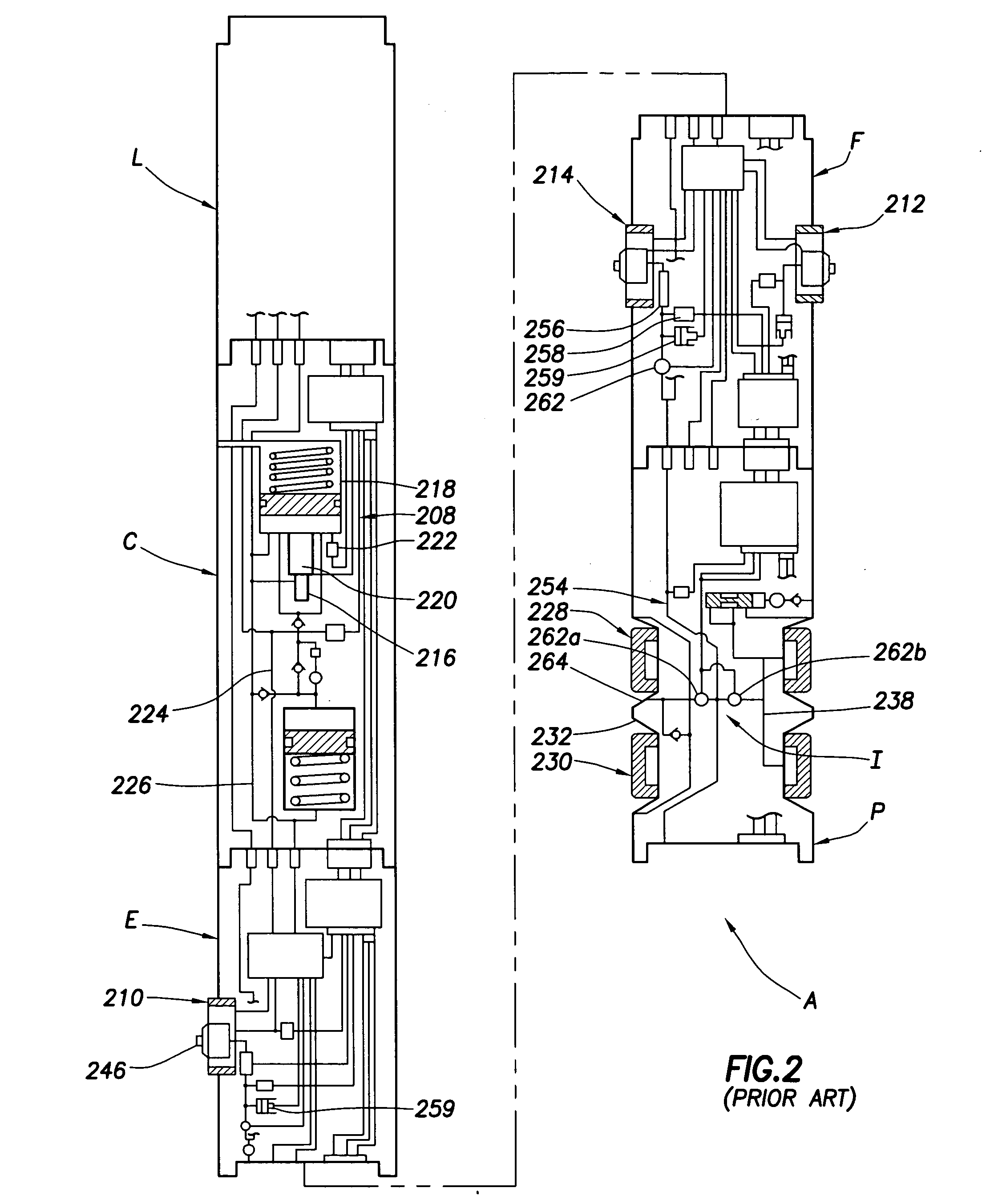
[0065] Turning now to prior art FIGS. 2 and 3, an example of an apparatus with which the present invention may be used to advantage is illustrated schematically. Other downhole tools, such as drilling, coiled tubing, completions or other tools may optionally be used. The apparatus A is a downhole tool that can be lowered into the well bore (not shown) by a wireline (not shown) for the purpose of conducting formation property tests. Apparatus A is described in greater detail in U.S. Pat. Nos. 4,860,581 and 4,936,139 assigned to Schlumberger and previously incorporated by reference herein. For information purposes, some details of the apparatus are described herein. The wireline connections to tool A as well as power supply and communications-related electronics are not illustrated for the purpose of clarity. The power and communication lines that extend throughout the length of the tool are generally shown at 208. These power supply and communication components are known to those ski...


PUM


Abstract

Conventional formation evaluation with dual inflatable packers includes the steps of pressurizing the packers so as to isolate an annular portion of the borehole wall, collecting one or more samples of formation fluid via the isolated portion of the borehole wall, and depressurizing the packers so as to permit movement of the mandrel within the borehole. A sampling method and apparatus that utilize one or more of the following to advantage is provided: restricting deformation of the packers during inflation using an annular bracing assembly; actively retracting the packers using ambient borehole pressure; and substantially centralizing the mandrel intermediate the packers so as to resist buckling of the mandrel.

Description

BACKGROUND OF THE INVENTION [0001] 1. Field of the Invention [0002] The present invention relates to inflatable packers having utility in downhole operations, particularly inflatable packers adapted for use in formation fluid sampling. [0003] 2. Background of the Related Art [0004] Once an oil well has been drilled, it is often necessary for the operator to obtain downhole data, such as pressure measurements and downhole fluid samples for analysis. These tasks are commonly accomplished with downhole tools, such as modular wireline tools or drilling tools with evaluation capabilities, that employ probes for engaging the formation and establishing fluid communication to make the pressure measurements and acquire the fluid samples. Fluid is typically drawn into the downhole tool through an inlet in the probe. In some instances, such as for tight, low permeability, formations, sampling probes are often replaced by dual inflatable packer assemblies. Examples of such probe and packer syst...

Claims


Application Information

Patent Timeline
IPC IPC(8): E21B33/12E21B33/127
CPCE21B33/1216E21B33/1243E21B33/1277E21B49/10E21B33/1208E21B33/126E21B33/127E21B33/128E21B47/01
Inventor BRENNAN, WILLIAM E. IIILONGFIELD, COLINARZOUMANIDIS, ALEXISCACCIALUPI, ALESSANDRO
Owner SCHLUMBERGER TECH CORP
Why Eureka
Try Eureka