
Ultraviolet cold cathode florescent lamp

a cold cathode florescent lamp and ultraviolet light technology, applied in the direction of discharge tube/lamp details, discharge tube luminescent compositions, discharge tube/lamp details, etc., can solve the problems of unfavorable skin cancer, uv incandescent lamps that may require frequent maintenance, and current spiral shapes and sizes of light tubes or envelopes adopted therein, so as to achieve effective and efficient cure of a certain type of nail gel

Inactive Publication Date: 2012-06-21
COSMEX
View PDF7 Cites 7 Cited by
  • Summary
  • Abstract
  • Description
  • Claims
  • Application Information

AI Technical Summary

Benefits of technology

[0007]In order to overcome the shortcomings described above, one aspect of the present invention is to provide an UV CCFL light bulb capable of curing an UV hardening or polymerizable gel such as an acrylic gel may respond to a UV irradiation to be polymerized or solidified from a liquid to a solid state safely and uniformly with an UV irradiation. It is also preferable that the UV irradiation provided by the UV CCFL lamp of the present invention is sufficient to cure a certain type of nail gel effectively and efficiently in terms of luminous efficacy (lm / W) required such as in comparison with the ones of a known incandescent or LED lamp. The irradiation is preferably of an illumination angle of 360 degrees such that the UV irradiation provided by the UV CCFL of the present invention is substaintially uniform in various directions.
[0010]Still another aspect of the present invention is to provide a UV CCFL lamp utilizing the abovementioned UV-excited phosphor and advantageously configured to provide a substantially uniform irradiation output. It is preferable that the lamp envelope, including its dimension and shape, is advantageously configured to facilitate the bombardment or reaction of UV light rays with said phosphor disposed in the lamp envelope such that a relatively uniform UV irradiation may be obtained.
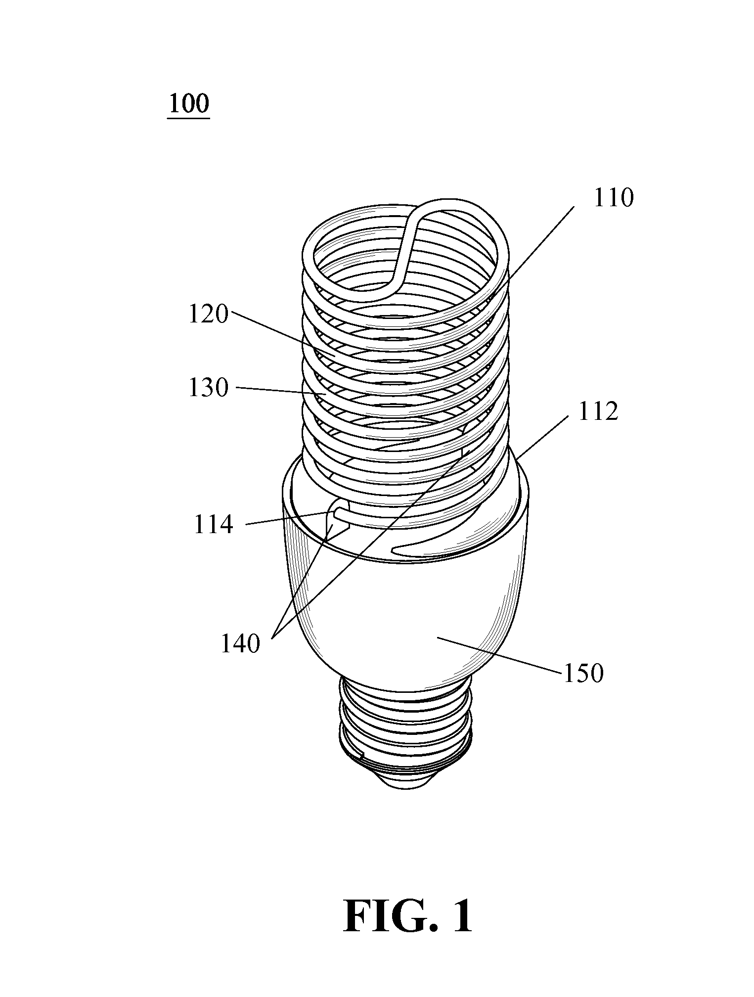
[0013]As UV irradiation provided by a UV CCFL lamp of the present invention is preferably to be uniform and of sufficient power or luminous efficacy, according to one embodiment of present invention, the lamp envelope enclosing the abovementioned exemplary embodiments of UV-excited phosphor to produce a non-UVC irradiation, preferably a UVA irradiation, may be advantageously configured to be of a spiral tubular shape having a substantially circular cross section with a diameter selected and manufactured to facilitate the bombardment of the phosphor power with the emission of ultraviolet rays initially produced by the discharge medium excited to a plasma vapor form such that a uniform irradiation output of UVA spectrum or wavelength of the UV CCFL lamp of the present invention may be obtained.
[0014]Furthermore, to advantageously provide a uniform UV irradiation output, preferably in a UVA spectrum range, the abovementioned UV-excited phosphor prepared to be disposed in a lamp envelope of the UV CCFL lamp of the present invention may be in a powder form such that the bombardment of the phosphor with the ultraviolet light ray produced by ion-excited vapor of the plasma of the discharge medium may be increased and enhanced. In one embodiment, the phosphor may comprise a composition of europium-doped boron strontium oxide (B4SrO7:Eu+) having a mean grain size between 12 μm and 18 μm. In another embodiment, the phosphor may comprise a composition of europium-doped strontium fluoborate (SrFB2O3.5:Eu2+) having a mean grain size between 5.5 μm and 11.5 μm.

Problems solved by technology

One is the hazard of having human skin exposed to UV rays under these UV incandescent lamps or bulbs may lead to undesirable skin cancer in a long run since UV incandescent lamps typically emit three types of UV light in reference to skin protection and these are UVA (wavelength 400 nm-315 nm), UVB (wavelength 315 nm-280 nm), and UVC (wavelength 280 nm-100 nm).
Another major drawback deals with the relatively short lifetime of UV incandescent lamps that may require frequent maintenance.
A typical UV incandescent lamp has a lifetime of 3,000 hrs (or approximately 4 months) and upon which replacements must be performed and may not be optimal if fixtures or machinery adopting such UV lamps include delicate components and / or electrical plugs and / or circuitries.
CFL lamps are known for being of relatively energy saving in the field of general lighting while capable of producing a sufficient illumination with great angles; however, the current spiral shapes and sizes of the light tube or envelope adopted therein tend to be problematic if any UV-excited compound is to be introduced therein to respond to mercury plasma excited and contained therein during operation in order to produce or achieve a desired uniform lighting with sufficient lumen output.
In other words, it is found that the current or standard shapes and structures of CFL cannot efficiently or desirably produce a uniform UV irradiation by simply introducing UV-excited compound therein to respond to or with the mercury ion vapor or plasma contained therein.
In fact, it is found that due to the limitation of current UV LEDs emitting UV irradiation in the UV spectrum ranges are far from being considered as efficient as other known LEDs in visible spectrums.
Furthermore, UV LEDs like most current LEDs are limited by their illumination angle as being a point light source, which may require multiple modules for an illumination area and in term may undesirably increase the overall material and installation costs, in comparison to the same illumination output and area given under incandescent or CFL lightings.
Greater power is required to produce a sufficient or desired UV irradiation from a current UV LED, which in term may too increase the operating temperature or junction temperature of the UV LED, making it undesirable or an unpractical solution to the current UV irradiation and application up to this very date.
However, yellowing of a cured artificial nail of gel type nails may still occur and may thus fail to meet aesthetic demands of consumers.
Another factor being that the curing or solidification process of typical nail gel generally requires a significant of process time and may or may not be involving and a photopolymerization initiator.

Method used


Image

  • Ultraviolet cold cathode florescent lamp
  • Ultraviolet cold cathode florescent lamp
  • Ultraviolet cold cathode florescent lamp

Examples


Embodiment Construction

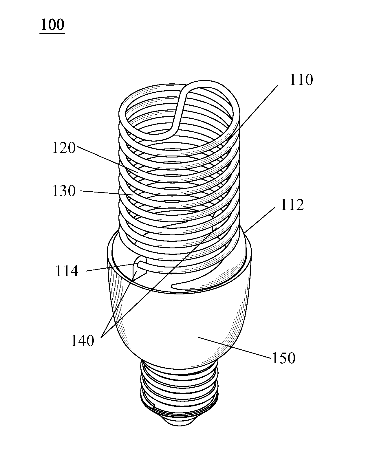
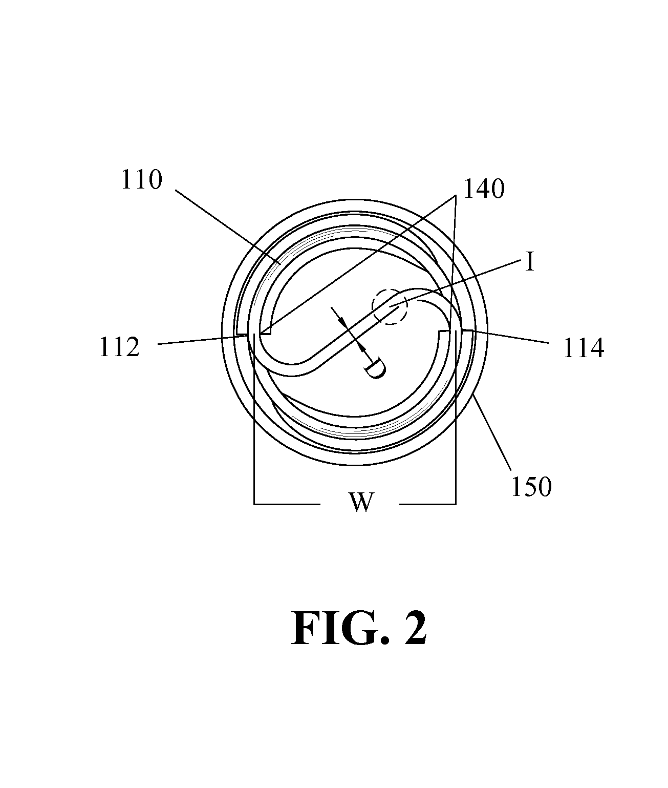
[0021]FIGS. 1 and 2 show an exemplary embodiment of a UV CCFL lamp 100 of the present invention, the UV CCFL lamp 100 is provided for curing a UV curable or polymerizable gel and more particularly, the UV CCFL lamp 100 may be advantageously provided for curing a nail gel in the field or application of nail art with a UV irradiation preferably in a non-UVC spectrum range such as wavelength of UVA (400 nm-315 nm) or UVB (315 nm-280 nm) to ensure a safer and healthier usage. In an explanatory example, the UV CCFL lamp 100 of the present invention may comprise a lamp envelope 110, a discharge medium 120 having ions excited to a plasma state by a high voltage electricity provided at discharge electrodes 140 attached to and configured on two ends 112, 114 of the lamp envelope 110. A UV-excited phosphor 130 may too be disposed within the lamp envelope 110 of the UV CCFL lamp 100 of the present invention and distributed to be in contact with said discharge medium 120 to provide a UV irradia...


PUM


Abstract

The present invention is related to a UV CCFL lamp, and more particularly, to a UV CCFL lamp for curing a nail gel with a UVA irradiation having a peak wavelength of such as 366 nm or 368 nm in the field of nail art. In order to provide a UV CCFL lamp capable generating ultraviolet light of high intensity and uniform lighting with great electrical safety and reliability, the UV CCFL lamp of the present invention comprises a translucent hermetic envelope configured to enclose a discharge medium and a UV-excited phosphor to generate the desired UV irradiation preferably in the UVA spectrum range. The discharge medium is preferably to be a mercury-ion vapor and distributed throughout and sealed within the lamp envelope to be excited to a plasma state and for producing a first emission spectrum of a UVC wavelength during operation; and the phosphor in contact with the mercury-ion vapor plasma preferably comprises a composition of either europium-doped boron strontium oxide (B4SrO7:Eu+) or europium-doped strontium fluoborate (SrFB2O3.5:Eu2+) for producing said UV irradiation in response to said first emission spectrum of the discharge medium. To provide a uniform UV irradiation output from the UV CCFL lamp of the present invention, the phosphor is advantageously prepared to be of a mean grain size of 8.5μm±3μm for SrFB2O3.5:Eu2+ and of 15μm±3μm for B4SrO7:Eu+.

Description

FIELD OF THE INVENTION[0001]The present invention relates to a ultraviolet (UV) curing lamp, and more particularly, to a UV cold cathode florescent lamp (CCFL) utilizing a UV-excited UV phosphor for converting UV wavelength of light to solidify a particular nail gel applied onto the nails of human fingers and toes as well as those of animal pets.BACKGROUND OF THE INVENTION[0002]The professional field of nail art has been widely introduced worldwide and has grown to adapt various new technologies as the development of both lighting and nail gel composition improves. In general, nail art may refer to the makeup or decoration of nails of fingers and toes. Conventional nail art may use either a resin or a gel type of artificial composition polymerizing at room temperature to form artificial nails. More advanced nail gel capable of forming or polymerizing into artificial nails in a relatively shorter duration of time may utilize a UV irradiation to enhance such curing or polymerizing pro...

Claims


Application Information

Patent Timeline
Patent Type & Authority Applications(United States)
IPC IPC(8): H01J63/04
CPCH01J61/327C09K11/774H01J61/44
Inventor LI, YU JEN
Owner COSMEX
Learn More