
Copper alloy wire and method for producing the same

a technology of copper alloy wire and copper alloy wire, which is applied in the direction of conductors, foundry patterns, and moulding apparatus, can solve the problems of insufficient ultimate tensile strength, and achieve the effect of increasing ultimate tensile strength

Active Publication Date: 2012-06-14
NGK INSULATORS LTD +1
View PDF3 Cites 6 Cited by
  • Summary
  • Abstract
  • Description
  • Claims
  • Application Information

AI Technical Summary

Benefits of technology

[0006]A main object of the present invention, which has been made to solve the above problem, is to provide a copper alloy wire with increased ultimate tensile strength.
[0007]As a result of an intensive study for achieving the above object, the present inventors have found that a copper alloy wire with high strength can be achieved by casting a copper alloy containing 3.0 to 7.0 atomic percent of zirconium into a bar-shaped ingot having a diameter of 3 to 10 mm using a pure copper mold and drawing the ingot to a reduction of area of 99.00% or more, thus completing the present invention.
[0012]These copper alloy wires have increased ultimate tensile strength. Although the reason for this effect remains uncertain, presumably the double fibrous structure, namely, the matrix phase-composite phase fibrous structure and the composite phase inner fibrous structure, makes the copper alloy wire densely fibrous to provide a strengthening mechanism similar to the rule of mixture for fiber-reinforced composite materials. Alternatively, presumably the amorphous phases present in the composite phases provide some strengthening mechanism.

Problems solved by technology

However, the copper alloy wires disclosed in PTLs 1 and 2 may have insufficient ultimate tensile strength, for example, if they are thinned, and there is therefore a need for a higher strength.

Method used


Image

  • Copper alloy wire and method for producing the same
  • Copper alloy wire and method for producing the same
  • Copper alloy wire and method for producing the same

Examples


example 1

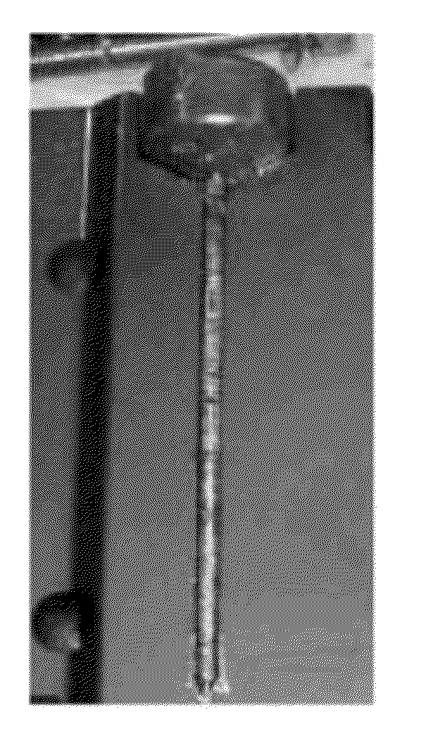
[0079]First, a copper-zirconium binary alloy containing 3.0 atomic percent of zirconium with the balance being copper was subjected to levitation melting in an argon gas atmosphere. Next, a pure copper mold having a round-bar-shaped cavity with a diameter of 3 mm was coated, and the melt of about 1,200° C. was poured and cast into a round-bar ingot at about 1,200° C. The diameter of the ingot was determined to be 3 mm by measurement using a micrometer. FIG. 6 is a photograph of the round-bar ingot. Next, wire drawing was performed by passing the round-bar ingot, which had been cooled to room temperature, through 20 to 40 dies having gradually decreasing hole diameters at room temperature so that the diameter after the wire drawing was 0.300 mm, thus producing a wire of Example 1. During the process, the drawing speed was 20 m / min. The diameter of the copper alloy wire was determined to be 0.300 mm by measurement using a micrometer. FIG. 7 is a photograph of a diamond die used for dr...

examples 2 to 4

[0080]A wire of Example 2 was produced in the same manner as in Example 1 except that wire drawing was performed so that the diameter after the wire drawing was 0.100 mm. In addition, a wire of Example 3 was produced in the same manner as in Example 1 except that wire drawing was performed so that the diameter after the wire drawing was 0.040 mm. In addition, a wire of Example 4 was produced in the same manner as in Example 1 except that wire drawing was performed so that the diameter after the wire drawing was 0.010 mm.

examples 5 to 9

[0081]A wire of Example 5 was produced in the same manner as in Example 1 except that a copper-zirconium binary alloy containing 4.0 atomic percent of zirconium with the balance being copper was used. In addition, a wire of Example 6 was produced in the same manner as in Example 5 except that wire drawing was performed so that the diameter after the wire drawing was 0.100 mm. In addition, a wire of Example 7 was produced in the same manner as in Example 5 except that wire drawing was performed so that the diameter after the wire drawing was 0.040 mm. In addition, a wire of Example 8 was produced in the same manner as in Example 5 except that wire drawing was performed so that the diameter after the wire drawing was 0.010 mm. In addition, a wire of Example 9 was produced in the same manner as in Example 5 except that wire drawing was performed so that the diameter after the wire drawing was 0.008 mm.


PUM

PropertyMeasurementUnit
widthaaaaaaaaaa
widthaaaaaaaaaa
mean atomic numberaaaaaaaaaa

Abstract

The zirconium content of the alloy composition of a copper alloy wire is 3.0 to 7.0 atomic percent; and the copper alloy wire includes copper matrix phases and composite phases composed of copper-zirconium compound phases and copper phases. The copper matrix phases and the composite phases form a matrix phase-composite phase fibrous structure and are arranged alternately parallel to an axial direction as viewed in a cross-section parallel to the axial direction and including a central axis. The copper-zirconium compound phases and the copper phases in the composite phases also form a composite phase inner fibrous structure and are arranged alternately parallel to the axial direction at a phase pitch of 50 nm or less as viewed in the above cross-section. This double fibrous structure presumably makes the copper alloy wire densely fibrous to provide a strengthening mechanism similar to the rule of mixture for fiber-reinforced composite materials.

Description

TECHNICAL FIELD[0001]The present invention relates to copper alloy wires and methods for producing copper alloy wires.BACKGROUND ART[0002]Known copper alloys for wires include copper-zirconium alloys. For example, PTL 1 proposes a copper alloy wire with improved electrical conductivity and ultimate tensile strength produced by subjecting an alloy containing 0.01% to 0.50% by weight of zirconium to solution treatment, drawing the alloy to the final diameter, and subjecting the wire to predetermined aging treatment. This copper alloy wire has Cu3Zr precipitated in copper matrix phases to achieve a high strength up to 730 MPa. In PTL 2, on the other hand, the present inventors have proposed a copper alloy containing 0.05 to 8.0 atomic percent of zirconium and having a two-phase structure in which copper matrix phases and eutectic phases of copper and a copper-zirconium compound are layered on top of each other and in which the adjacent copper matrix phase crystal grains contact intermi...

Claims


Application Information

Patent Timeline
Patent Type & Authority Applications(United States)
IPC IPC(8): C22C9/00C22F1/08B22D25/02
CPCC22C1/02H01B1/026C22F1/08C22C9/00
Inventor MURAMATSU, NAOKUNIKIMURA, HISAMICHIINOUE
Owner NGK INSULATORS LTD
Learn More