
Joining magnesium with reinforced polymer composite fasteners

a technology of reinforced polymer and composite fasteners, which is applied in the direction of fastening means, manufacturing tools, mechanical equipment, etc., can solve the problems of unreinforced polymers, fasteners that do not create potential galvanic corrosion between, and may not offer sufficient strength, etc., to achieve enhanced strength, significant strength to the joint, and enhancement of lap shear strength

Active Publication Date: 2012-05-24
GM GLOBAL TECH OPERATIONS LLC
View PDF13 Cites 8 Cited by
  • Summary
  • Abstract
  • Description
  • Claims
  • Application Information

AI Technical Summary

Benefits of technology

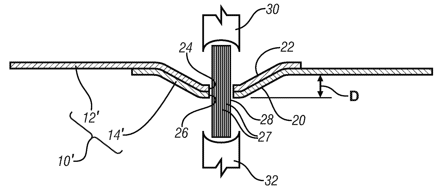
The patent text describes a method for joining overlapping thin workpieces, such as sheet metal, using fiber-reinforced polymer fasteners. The fasteners offer a higher strength than unreinforced polymer fasteners, but they require deformation of the workpieces to mechanically engage them. The method involves using two approaches: reinforcing the polymer fasteners with fibrous reinforcements or deforming the workpieces so that they mechanically engage each other. The use of fiber-reinforced polymer fasteners in combination with deformed workpieces can create a strong lap joint. The patent also describes the use of thermoset polymers, which offer better creek resistance and dimensional stability than thermoplastics. The fasteners can be formed in place by inserting short rod-like lengths of the fiber-reinforced polymer into holes in the workpiece stack. The length of the body should be equal to the thickness of the workpiece stack plus a distance equal to between 2.4 and 4 times the hole diameter. The method can be used in automotive applications involving high temperatures.

Problems solved by technology

Such fasteners do not create a potential for galvanic corrosion between the fastener and magnesium.
But the lap-shear strength of lap joints, formed in generally planar workpieces is primarily dependent on the fastener strength, and unreinforced polymers, in dimensions similar to those of metal fasteners, may not offer sufficient strength.

Method used


Image

  • Joining magnesium with reinforced polymer composite fasteners
  • Joining magnesium with reinforced polymer composite fasteners
  • Joining magnesium with reinforced polymer composite fasteners

Examples


first embodiment

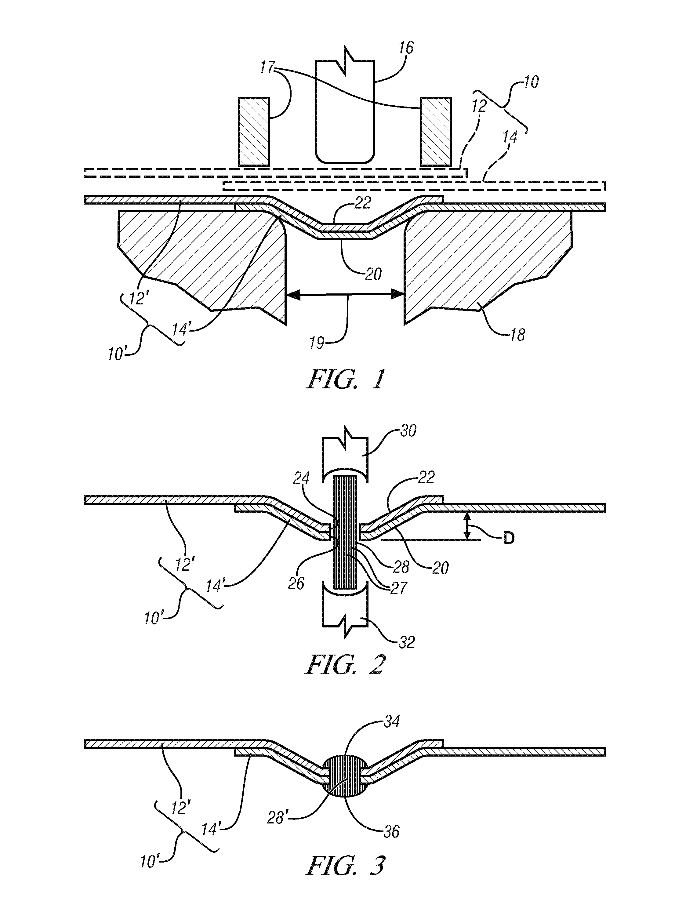
[0050]FIG. 1 shows, in sectional view, the invention. A workpiece stack 10, consisting of partially-overlapping sheet workpieces, 12 and 14, shown in ghost, supported by die 18 have been indented by flat-bottomed punch 16. Flat-bottomed punch 16 is centered over the throat, or die opening, 19 of die 18. As punch 16 is advanced, first into contact with the workpieces and then into die throat opening 19 the workpieces are subjected to deformation out of the plane of the sheet. Typically buckling of the sheets will be inhibited through the use of binder 17 positioned in opposition to die 18. This out-of-plane deformation of sheets 12 and 14 may form nesting, flat-bottomed, sloping-wall features 20 and 22 in deformed workpiece stack 10′ consisting of sheets 12′ and 14′. Punch 16 and die throat 19 are of complementary cross-section. It will be appreciated that if punch 16 and die throat 19 are circular in cross-section that flat-bottomed, sloping wall features 20 and 22 will have the for...

second embodiment

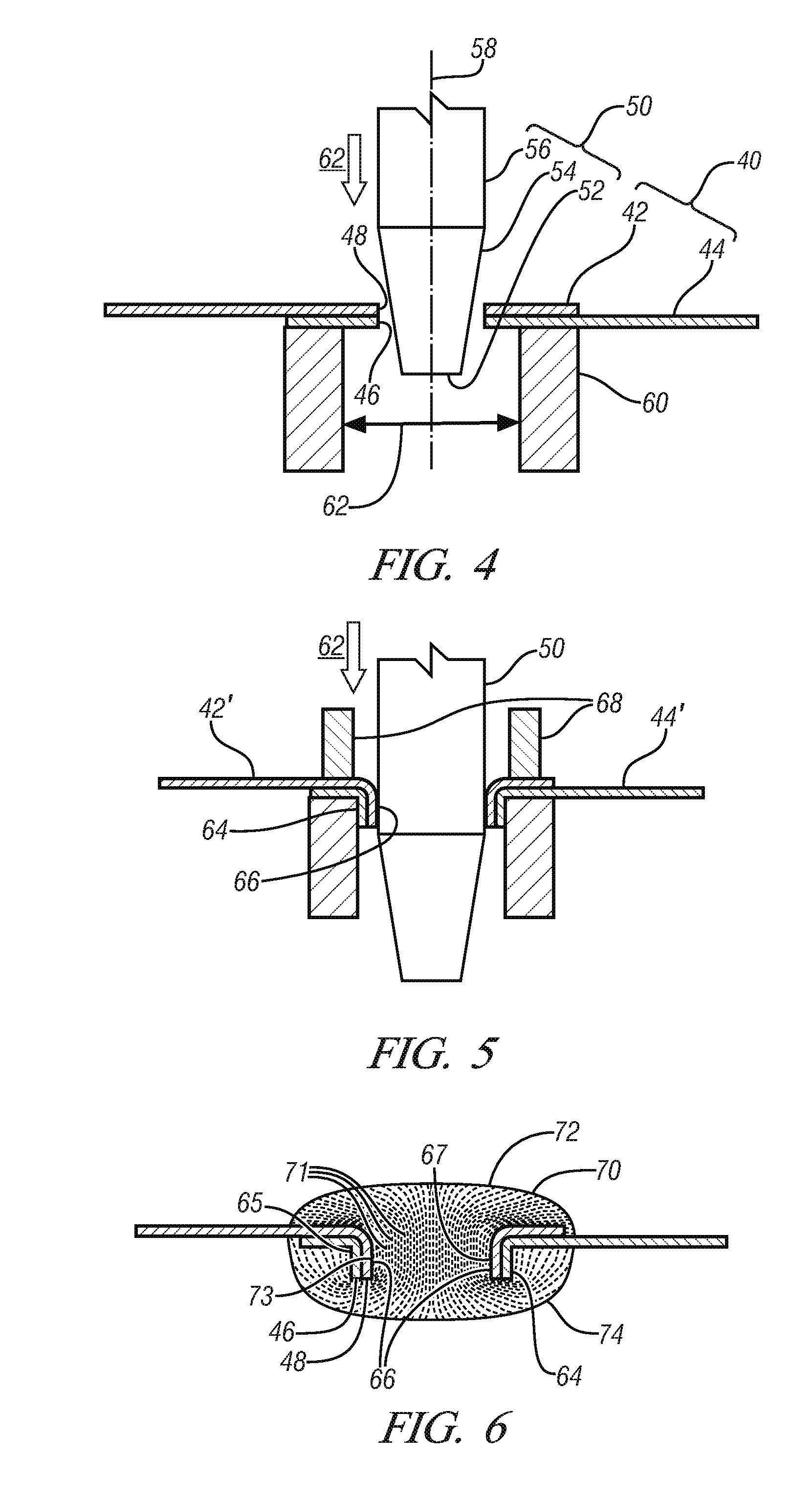
[0056]the invention is shown in FIG. 4 which shows, in sectional view, a workpiece stack 40 consisting of workpiece sheets 42 and 44 at least one of which is a magnesium alloy. Aligned, substantially commonly-dimensioned openings bounded by cut edges 48 and 46, have been made in the sheets by one of the previously-described approaches, and workpiece stack 40 has been positioned on die 60, with openings bounded by cut edges 48 and 46 centrally positioned in die throat 62.

[0057]Punch 50, consisting of shank 56, taper 54 and end 52, advances along symmetry axis 58, central to the die throat and substantially perpendicular to the sheet surfaces, in the direction indicated by arrow 62. End 52 of punch 50 is sized and constructed to pass through the opening as is a portion of tapered punch section 54. However the relative dimensions of punch, die opening and sheet stack thickness are such that continued advance of punch 50 will cause tapered section 54 to first engage and then downwardly ...

third embodiment

[0062]A third embodiment is illustrated in FIGS. 7-9. FIG. 7 illustrates the further deformation of flanges 64 and 66 (FIG. 5) by the shaping surface 82 of form tool 76 which further bends the flanges to bend them back on themselves to form nested, rolled-over, flanges 64′ and 66′. The end 81 of form tool 76, when directed as shown by arrow 84, is sized and constructed to enter the hole formed by inner walls 67 of inner flange 66 (FIG. 6) so that the cut surfaces 46 and 48 contact curved shaping surface 82 of tool 80. Continued motion of tool 76 will impart a moment to flanges 64 and 66 curling or bending them back on themselves to form rolled-over flanges. Backing plate 75 supports the opposing surface of the workpiece stack, and may, optionally, include features such as protrusion 78 for engagement with cavity 80 of tool 76 for guidance of tool 76.

[0063]It will be appreciated that the deformation required to form such rolled-over flanges is considerable and that significant strain...


PUM

PropertyMeasurementUnit
temperatureaaaaaaaaaa
crystallization temperatureaaaaaaaaaa

Abstract

A method is disclosed for forming corrosion-resistant joints in a plurality of overlapping thin metal sheet workpieces, at least one of which comprises at least 85% by weight of magnesium sheets. The fastener is a fiber-reinforced polymer rod shaped and sized for insertion into a coaxial opening formed in each sheet and subsequently upset on each end to form a head. The workpiece sheets are deformed to form mechanically-interfering features which cooperatively complement the strength of the fastener, under at least some joint loading patterns. The method may be used for other workpiece and fastener compositions.

Description

TECHNICAL FIELD[0001]This invention pertains to methods of forming high lap shear strength joints in thin sheet metal components, one or more of which may be a magnesium alloy, using fiber-reinforced thermoplastic or thermosetting fasteners in cooperation with mechanically-interfering structures formed by deforming the sheets.BACKGROUND OF THE INVENTION[0002]The increasing application of high strength-to-weight-ratio materials is one of several strategies adopted in pursuit of increased automobile fuel economy, and current automobiles incorporate a wide variety of such materials including high strength steel, high performance aluminum alloys and magnesium alloys. Among this variety of higher strength-to-weight-ratio materials, magnesium and its alloys are attractive, due to the low density of magnesium coupled with their ability to achieve acceptably high strength when suitably processed.[0003]Magnesium is the most chemically active of the commonly-used automotive structural metals ...

Claims


Application Information

Patent Timeline
Patent Type & Authority Applications(United States)
IPC IPC(8): B21J15/02
CPCB29C70/845F16B5/04B21D39/031Y10T29/49954Y10T29/49936Y10T29/49957Y10T29/49956
Inventor BERGER, ELISABETH J.FOSS, PETER H.LEV, LEONID C.CARTER, JON T.
Owner GM GLOBAL TECH OPERATIONS LLC
Learn More