
Method of sige epitaxy with high germanium concentration

a technology of germanium concentration and epitaxial layer, which is applied in the direction of single crystal growth, electrical equipment, chemistry apparatus and processes, etc., can solve the problems of increasing equipment cost and process complexity, limited germanium concentration improvement, etc., and achieves stable pressure

Inactive Publication Date: 2012-05-10
SHANGHAI HUAHONG GRACE SEMICON MFG CORP
View PDF3 Cites 19 Cited by
  • Summary
  • Abstract
  • Description
  • Claims
  • Application Information

AI Technical Summary

Benefits of technology

The present invention provides a method for forming a SiGe epitaxial layer with high germanium concentration. This method allows for the growth of a SiGe epitaxial layer with a germanium concentration of -25 to -35 atomic percent without defects. The method involves reducing the ratio of silane to germane and maintaining a low level of silane flow to achieve a high germanium concentration while keeping the SiGe epitaxial layer defect-free. The method can be carried out at a lower temperature and utilizing existing equipment without additional germanium source and flowmeters. The resulting SiGe epitaxial layer is stable and defect-free, meeting the requirements of devices.

Problems solved by technology

In theory, the germanium concentration should be as high as possible, but according to the literatures available as so far, the germanium concentration is generally less than 20% (atomic percentage), moreover, there is no disclosed specific growing method for SiGe epitaxial layer with higher germanium concentration for the following restrictions: first, since SiGe epitaxy is a process based on a Si epitaxial process and increases the concentration of germanium, there could be a large mismatch, which may easily cause defects; second, although the germanium concentration can be improved by reducing the epitaxial growth temperature, the epitaxial growth rate is greatly reduced, for example, according to the results of experiments, if the growth temperature decreases 30° C., the growth rate is reduced to one-third of the original, therefore the throughput will be reduced, meanwhile the germanium concentration improved by the way of reducing the epitaxial growth temperature is limited, e.g. when the epitaxial growth temperature decreases 30° C., the germanium concentration is only improved by 2%; third, although the germanium concentration can also be improved by increasing germane flow, the improvement of the germanium concentration is limited because the epitaxial growth rate will increase as the germane flow increases, for example, a maximum germane flow only contributes to 2% of the increase of the germanium concentration.
In present practice of 10%-20% germanium concentration, two germane flowmeters should be arranged to obtain a germanium gradient (i.e., the germanium concentration gradually declines from high to low), therefore at least three germane flowmeters are needed to obtain an epitaxial layer with high germanium concentration, which will increase equipment cost and process complexity.

Method used


Image

  • Method of sige epitaxy with high germanium concentration
  • Method of sige epitaxy with high germanium concentration
  • Method of sige epitaxy with high germanium concentration

Examples


embodiment 1

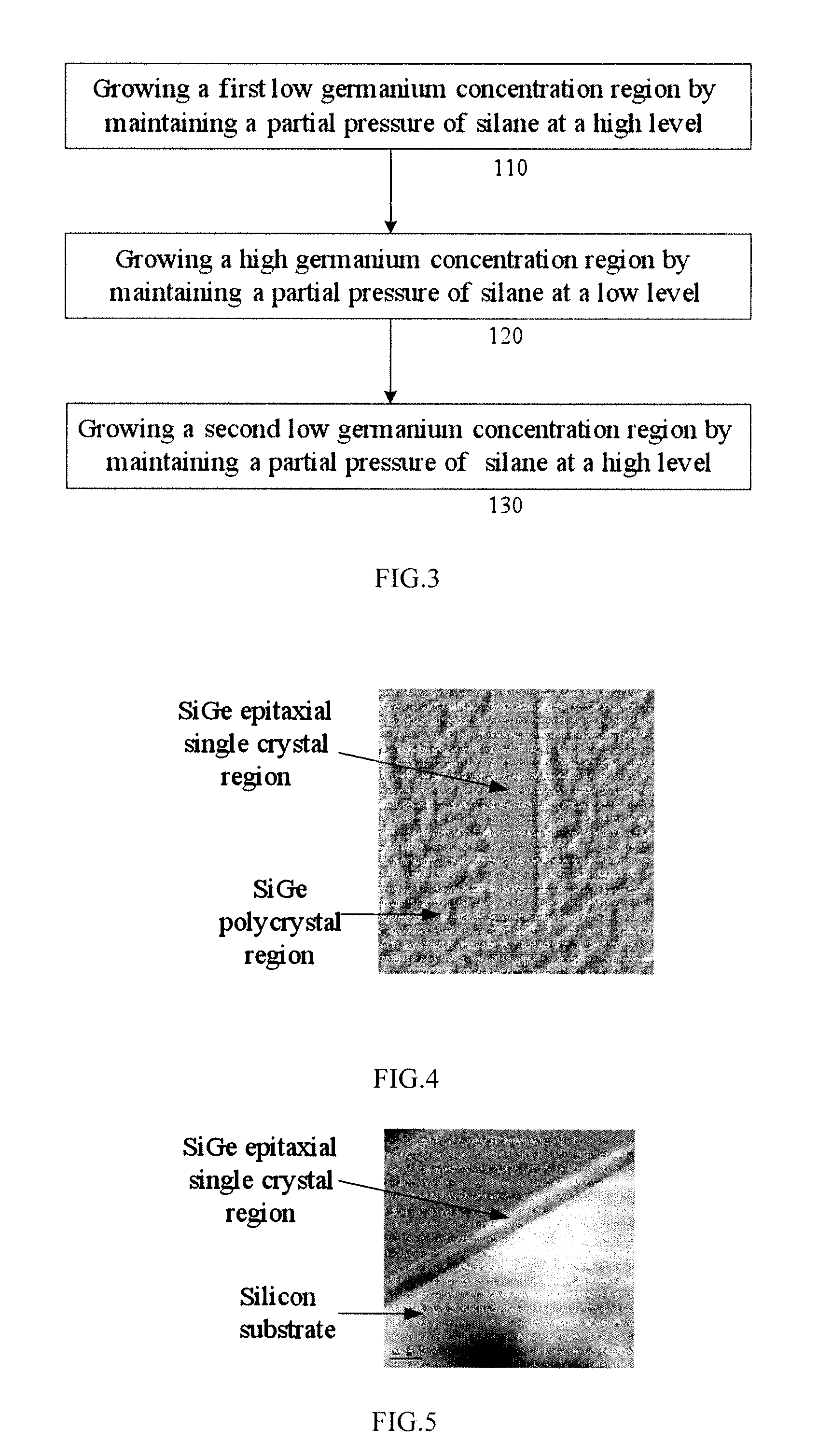
[0028]for forming the trapezoidal distribution of germanium concentration as shown in FIG. 1, first grow the low germanium concentration region 6 (Step 110) by maintaining a partial pressure of silane at a high level (the ratio of a silane flow to a germane flow of 1 / 3.5˜1 / 0, 1 / 0 indicates that the germane flow is minimized to 0 sccm, the germane flow is 0˜100 sccm and the silane flow is 50˜200 sccm); then, switch the partial pressure of silane to a low level (the ratio of the silane flow to the germane flow is 1 / 20˜1 / 5, the silane flow is 20˜50 sccm and the germane flow is 300˜500 sccm) to grow the high germanium concentration region 5 (Step 120); switch the partial pressure of silane again to a high level (the ratio of the silane flow to the germane flow is 1 / 3.5˜1 / 0, 1 / 0 indicates that the germane flow is minimized to 0 sccm, the germane flow is 0˜100 sccm and the silane flow is 50˜200 sccm) to grow another low germanium concentration region 4 (Step 130); finally form a depth dis...

embodiment 2

[0029]for forming the trapezoidal distribution of germanium concentration shown in FIG. 1, first grow a Si buffer layer 3 (not containing germanium, i.e. having a germanium concentration of zero) (Step 110) by maintaining a partial pressure of the silane at a high level (the first silane partial pressure, i.e. the ratio of the silane flow to the germane flow is 1 / 0, e.g., the germane flow is 0 sccm and the silane flow is 50˜200 sccm); then switch the partial pressure of silane to a low level (the ratio of the silane flow to the germane flow is 1 / 20˜1 / 5, the silane flow is 20˜50 sccm and the germane flow is 300˜500 sccm) to grow a SiGe layer 2 (Step 120); switch the partial pressure of silane again to a high level (the ratio of the silane flow to the germane flow is 1 / 0, e.g., the germane flow is 0 sccm and the silane flow is 50˜200 sccm) to grow a Si capping layer 1 (not containing germanium, i.e. having a germanium concentration of zero) (Step 130); finally form a depth distributio...


PUM

PropertyMeasurementUnit
concentrationaaaaaaaaaa
partial pressureaaaaaaaaaa
high-frequencyaaaaaaaaaa

Abstract

The present invention discloses a method of SiGe epitaxy with high germanium concentration, a germanium concentration can be increased by reducing the percentage of silane and germane during introduction silane and germane. With the same flow of germanium source, the germanium concentration is significantly increased as the germane flow is reduced, therefore a defect-free SiGe epitaxial film with a germanium atomic percentage of 25˜35% can be obtained. The present invention can balance epitaxial growth rate and germanium doping concentration by using existing equipments to obtain a high germanium concentration, and the epitaxial growth rate is only reduced a little, which can keep the SiGe epitaxial layer having no defect to meet the requirements of devices and can maintain sufficient throughput.

Description

CROSS-REFERENCES TO RELATED APPLICATIONS[0001]This application claims the priority of Chinese patent application number 201010533250.3, filed on Nov. 5, 2010, the entire contents of which are incorporated herein by reference.TECHNICAL FIELD[0002]The present invention relates to a semiconductor manufacturing method, especially to a method of forming SiGe epitaxial layer with high germanium concentration.BACKGROUND OF THE INVENTION[0003]Silicon-germanium (SiGe) has become another important semiconductor material other than Si and GaAs and has a better performance than pure Si material. The manufacturing process of SiGe is compatible with a silicon process. Electrical performances of SiGe heterojunction bipolar transistor (HBT) can nearly reach the same level as those of the same kind of devices made of compound semiconductor material like GaAs. Therefore, SiGe HBT has a broad application prospect in the field of RF (radio frequency) especially ultra high frequency. Moreover, SiGe HBT ...

Claims


Application Information

Patent Timeline
Patent Type & Authority Applications(United States)
IPC IPC(8): H01L21/20
CPCC30B29/52C30B25/02
Inventor MIU, YANJI, WEI
Owner SHANGHAI HUAHONG GRACE SEMICON MFG CORP
Learn More