
Fine-grained Clock Skew Tuning in an Integrated Circuit

a clock skew and integrated circuit technology, applied in the field of electrical, electronic and computer arts, can solve problems such as unpredictability of the circuit, invalidation of the previous data waiting, and “setup violation”

Active Publication Date: 2012-05-03
AVAGO TECH INT SALES PTE LTD
View PDF7 Cites 9 Cited by
  • Summary
  • Abstract
  • Description
  • Claims
  • Application Information

AI Technical Summary

Benefits of technology

[0007]Principles of the invention, in illustrative embodiments thereof, advantageously allow fine-grained clock skew balancing in an IC to be performed in a low-power, footprint-compatible manner, without the need to move cells, change cell sizes or modifying chip-level routing. Accordingly, embodiments of the invention enable fine-grained tuning of clock tree delays without impacting OCV or chip floorplan.

Problems solved by technology

If large enough, clock skew can cause errors to occur in the circuit or cause the circuit to behave unpredictably.
If the destination flip-flop receives a clock transition later than the source flip-flop, and if the logic path delay is short enough, then the data signal might arrive at the destination flip-flop before the clock transition, invalidating the previous data waiting there to be clocked through.
This is often referred to as a “hold violation,” since the data is not held long enough at the destination flip-flop to achieve a valid output result.
If the data fails to reach the destination flip-flop before the next clock transition, a “setup violation” occurs, since the new data was not set up and stable prior to the arrival of the next clock transition.
The task of correcting clock skew is made more difficult by the interaction of these and other characteristics.
Unfortunately, however, this approach suffers from area, power and complexity penalties, among other disadvantages.
Disadvantages of this approach include a significant performance reduction due, at least in part, to slower clock speeds.
This approach is undesirable, however, in that the buffers increase overall power consumption and OCV in the IC, and furthermore require additional IC area, among other disadvantages.

Method used


Image

  • Fine-grained Clock Skew Tuning in an Integrated Circuit
  • Fine-grained Clock Skew Tuning in an Integrated Circuit
  • Fine-grained Clock Skew Tuning in an Integrated Circuit

Examples


Embodiment Construction

[0020]The present invention will be described herein in the context of illustrative clock skew balancing and / or correction architectures. It should be understood, however, that the present invention is not limited to these or any particular clock skew balancing and / or correction circuit arrangements. Rather, the invention is more generally suitable for use in any circuit application in which it is desirable to provide improved performance, at least in terms of avoiding clocking-related problems such as clock skew, and the accompanying violation of setup and hold times associated therewith. In this manner, techniques of the present invention provide fine-grained clock skew balancing in an IC without increasing power consumption and OCV, and without impacting chip floorplan or changing chip-level routing.

[0021]Embodiments of the present invention thus offer significant advantages over conventional clock skew balancing and / or correction methodologies. Moreover, it will become apparent ...


PUM


Abstract

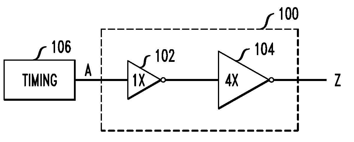
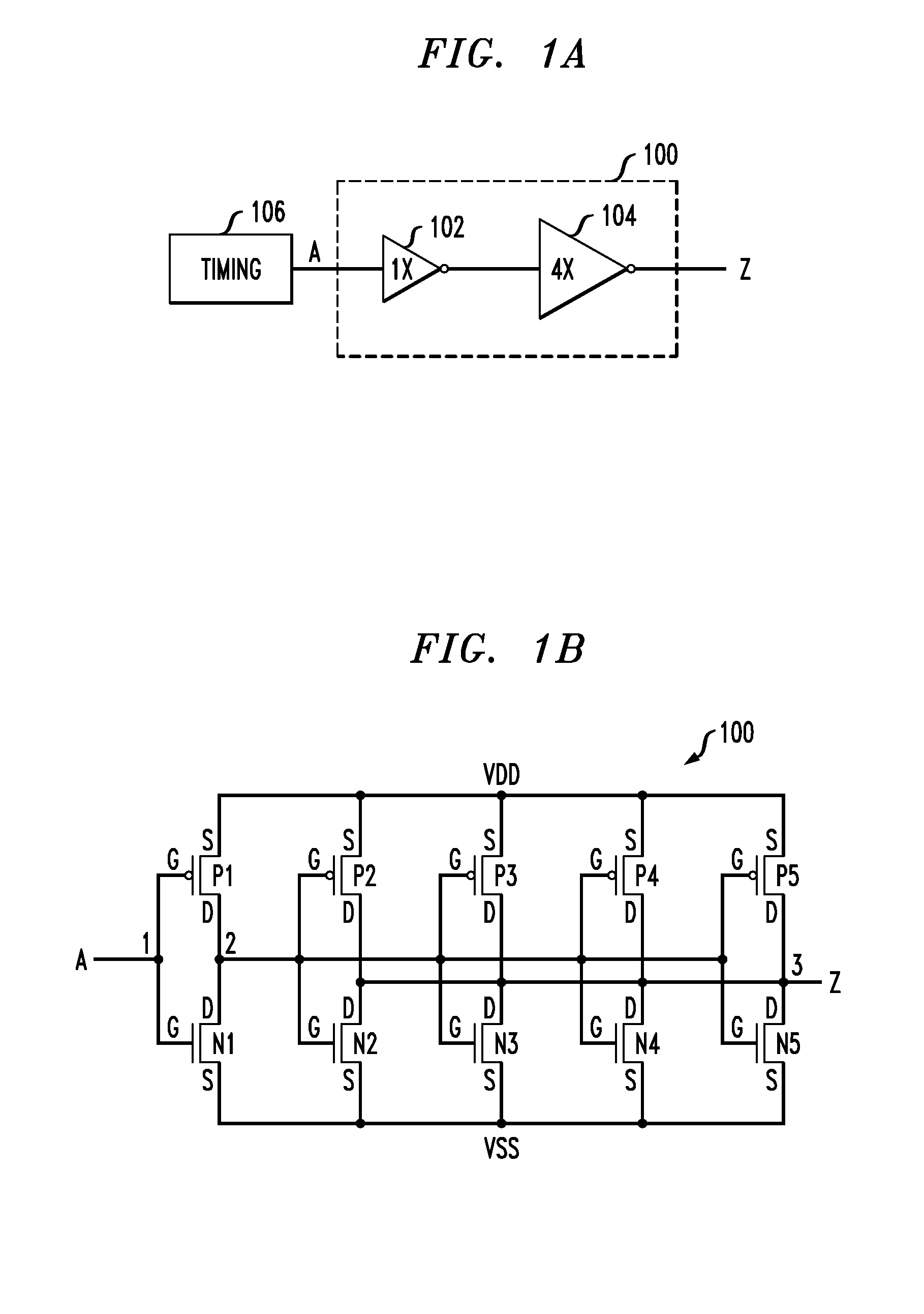
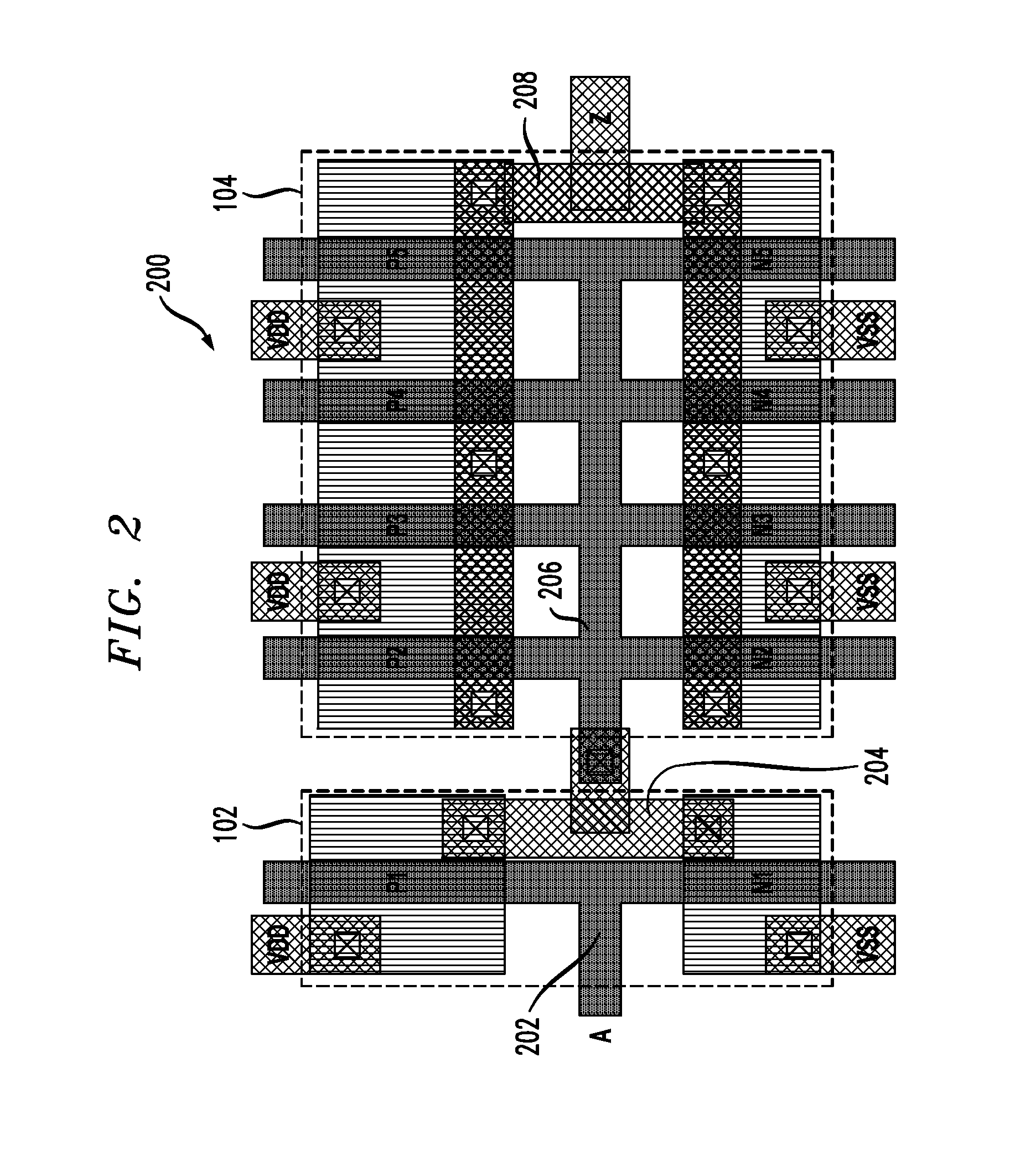
An apparatus for controlling clock skew in an integrated circuit (IC) includes timing circuitry operative to generate a clock signal for distribution in the IC and at least one buffer circuit operative to receive the clock signal, or a signal indicative of the clock signal, and to generate a delayed version of the clock signal as an output thereof. The buffer circuit includes at least first and second inverter stages and a resistive-capacitive (RC) loading structure. An output of the first inverter stage is connected to an input of the second inverter stage via the RC loading structure. The buffer circuit has a delay associated therewith that is selectively varied as a function of one or more adjustable characteristics of the RC loading structure. Clock skew in the IC is controlled as a function of the delay of the buffer circuit.

Description

FIELD OF THE INVENTION [0001]The present invention relates generally to the electrical, electronic, and computer arts, and more particularly relates to balancing clock skew in an integrated circuit (IC).BACKGROUND OF THE INVENTION[0002]The arrival of clock signals at various nodes in a circuit should be precisely coordinated to ensure accurate transfer of data and control information in the circuit. Clock skew is a phenomenon, primarily in synchronous circuits, in which the clock signal, generally sent from a common clock circuit, arrives at different circuit nodes at different times. This is typically due to three primary causes. The first is a material flaw which causes a signal to travel faster or slower than anticipated. The second is distance; if the signal is required to travel the entire length of a circuit, it will likely (depending upon the size of the circuit) arrive at different parts of the circuit at different times. The third is the number of non-sequential (combinati...

Claims


Application Information

Patent Timeline
IPC IPC(8): H03H11/26
CPCG06F1/10H03K2005/00215H03K5/133
Inventor BROWN, JEFFREY S.TURNER, MARK FRANKLIN
Owner AVAGO TECH INT SALES PTE LTD
Learn More