Because of the temperatures and duty cycles involved in many of these applications, many metallic tube materials are rapidly degraded so that tube deterioration or non-functionality requires replacement of the tubes in question.
However, as tubes grew ever smaller for a certain functions, the
insertion of linings became more difficult.
A major problem with arc cladding or oxy
acetylene torch cladding is that the surface developed thereby is extremely rough and irregular, requiring substantial
machining (clean-up) to render the surface thickness sufficiently uniform and smooth for many uses.
Also, as tube sizes decreased, traditional arc or
torch cladding became impossible.
Consequently, for many applications, cladding the interior of tubes was not an option.
However, certain problems remained, especially with respect to plasticating barrels having relatively small diameters.
With the vastly increasing use of plastics in the last half century, the demand for such extruders has become substantially greater, and the
processing conditions have become far more severe.
This is no longer the case due to the more complex and corrosive materials being processed and the need for plasticating barrels having smaller diameters.
Both the
barrel and screw of plasticating barrels are subject to wear from
metal-to-
metal contact and from
abrasive and / or corrosive fillers in the plastic or rubber compounds.
There are a number of disadvantages to these techniques.
Furnaces configured for rotating equipment are very expensive and require extensive maintenance.
Further, even when the furnaces are functioning properly, set up for the
coating of each
barrel is an awkward and time-consuming process.
This creates severe limitations on the liner materials that can be used.
As a result, abrasion-resistant and
corrosion-resistant materials are limited to formulas that melt at a lower temperature than the
barrel substrate.
In many cases the optimum barrel substrate and liner materials preferred for the materials to be handled, cannot be used together.
This lowers the strength of the annealed backing material.
Unfortunately, very high strengths are now required for many
high stress applications, such as plasticating barrels.
Such barrels can be subject to internal pressures of 40,000 psi or higher, and temperatures up to 700° F. These conditions often require the installation of a
high pressure sleeve at considerable expense.
However, greater expense is incurred, including greater
processing times and more complex manufacturing facilities.
As a result, the resulting lining is far more susceptible to wear caused by abrasion than if the
metal carbide particles are properly located on or very near the inner surface of the lining, or evenly distributed throughout the thickness of the lining or cladding.
Further, the high barrel temperatures that are reached during centrifugal
casting make it difficult to maintain the barrel straightness and integrity, which are critical to the subsequent plastic
processing operation.
Straightening of the barrel cannot be done by conventional straightening presses because reverse bending cracks the relatively brittle liner.
The rotational
casting process requires a long time to heat up the liner and barrel substrate.
This causes added expense in labor and electrical costs.
Because a centrifugal lining process can only be successful in a very
narrow range of processing times and temperatures, the results are often not satisfactory.
High temperatures and long time periods spent at these temperatures cause
dilution by migration of the substrate material into the barrel lining material or matrix.
This causes reduced
hardness and poor abrasion resistance.
Also substrate migration of the base iron material can cause poor
corrosion resistance in certain applications.
Extended periods at high temperatures also cause the metal
carbide particles
coating the inner surface of the liner to melt into solution in the matrix matter (constituting the liner), rendering the
carbide particles useless for anti-abrasion purposes.
When temperatures are too low and the time periods at proper processing temperatures are too short, an inadequate bond can result.
Such an inadequate bond means that the liner may become separated from the barrel substrate or backing material.
This condition could render the entire barrel useless for any purpose.
Further, in some cases, portions of the liner may come dislodged, corrupting the molten plastic and / or
fouling the screw pushing the molten plastic through the barrel.
In either case, the barrel is subject to major failure, and the plastic processed therein ruined.
Even if the lined tube or barrel is not going to be used in plasticating applications, the dislodging of the liner with respect to the base material can prove problematic.
For example, in boiler applications the base material of the tube could be prematurely corroded.
Liquid running through the tube may be hindered to the point that essential
heat transfer properties are compromised, and loose liner material could be stripped away, corrupting the overall water carrying system.
Conventional MIG or TIG cladding of the inside
diameter (ID) of barrels can be done to form metallurgical bonds, but it is more difficult to get such cladding heads into smaller
diameter barrels.
The area affected by heat is much greater than for
laser cladding, and the cladded surface is poorer than that resulting from laser cladding.
This results in far greater expense for post-clad finishing compared to the “near-
net shape” of laser-cladding.
However, rapid cooling can lead to difficulties under certain circumstances, as explained infra.
In certain applications, such as plasticating barrels, a true weld would be inappropriate because of the higher levels of migration or
dilution.
This method is limited to short longitudinal lengths of clads, as are generally required in boiler repair.
Powder is difficult to introduce in the horizontal position because, without
gravity assist, it tends to clog and interrupts cladding.
All of the aforementioned systems must have extensive auxiliary services introduced from the laser head end of the tube because access from the opposite end is not available and cannot be coordinated with the activity provided from the laser end.
Consequently,
size reduction for such cladding devices is severely limited.
As a result,
size reduction of the overall cladding apparatus is very problematical, and cannot accommodate some smaller sizes used for plasticating barrels.
However, there are number of drawbacks that still exist.
For example, in a horizontally-positioned tube,
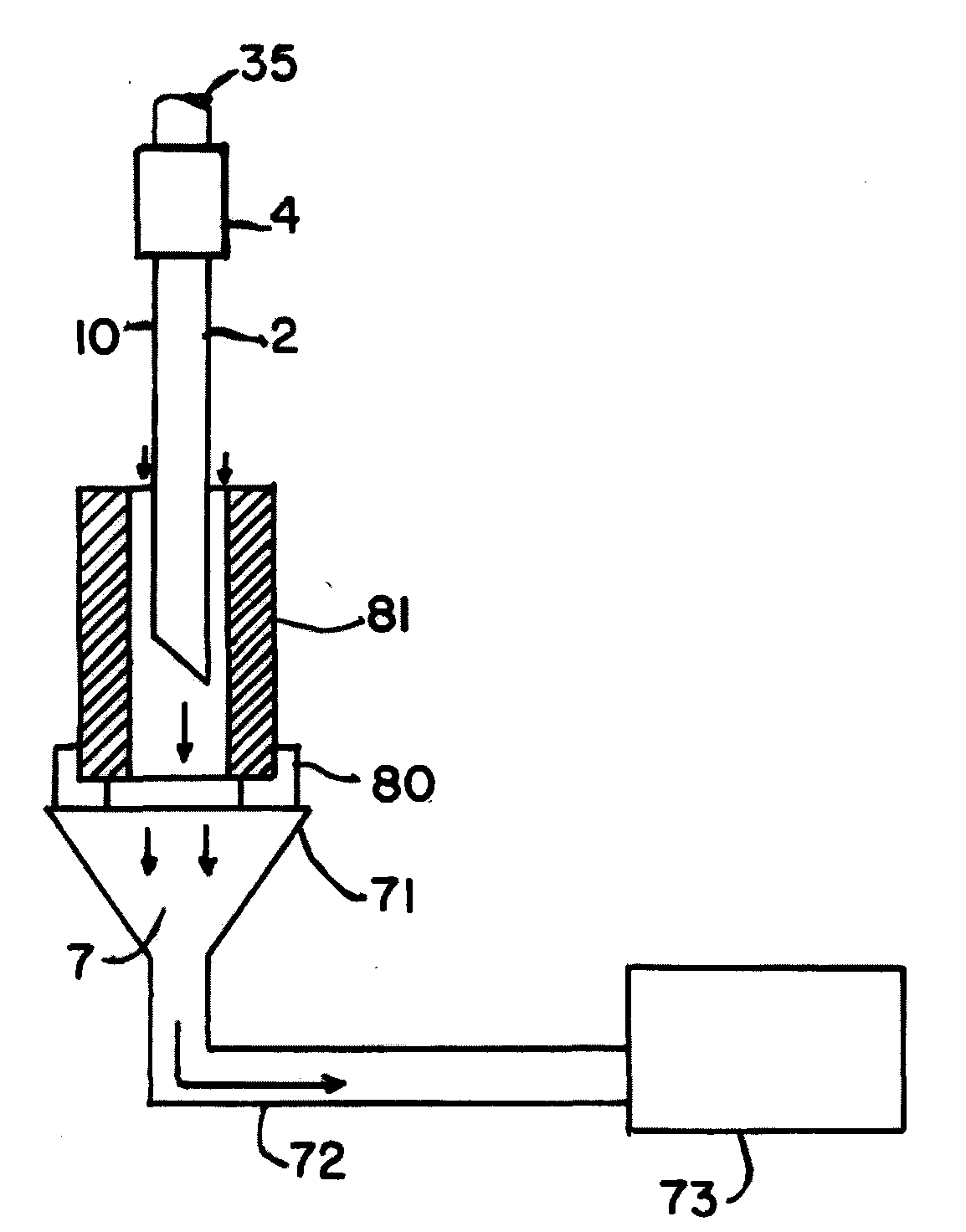
smoke and debris tend to accumulate due to the force of gravity, especially if the tube is long and the cladding head, rather than the tube, is moving.
This accumulation of
smoke and debris compromises the speed of the cladding process, results in wasted cladding
powder, and even degrades the cladding due to accumulated debris, which can occur even in a
spinning tube.
Also, in horizontally aligned tubes, the best cladding angles can sometimes be hard to obtain, thereby resulting in lost energy and a slower cladding process.
Reflection of laser energy from the smooth, cladded surface that is the object of laser cladding, can also damage equipment as well as waste energy.
Unfortunately, conventional cladding techniques permit migration of these carbide particles from the surface of the clad to positions deeper in the clad, where the particles are far less effective.
Also, conventional cladding techniques usually result in the loss of many of the carbide particles used in the process, thereby entailing substantial unnecessary expense.
Such techniques can be very extensive in nature and can greatly raise the price and complexity of the overall manufacturing process.
Also, there is the well-known problem of cracked laser clads due to overly-rapid cooling or uneven cooling.
This is not addressed in the examples of conventional art, and can be a major problem with laser cladding, depending upon the types of materials used in the cladding process.
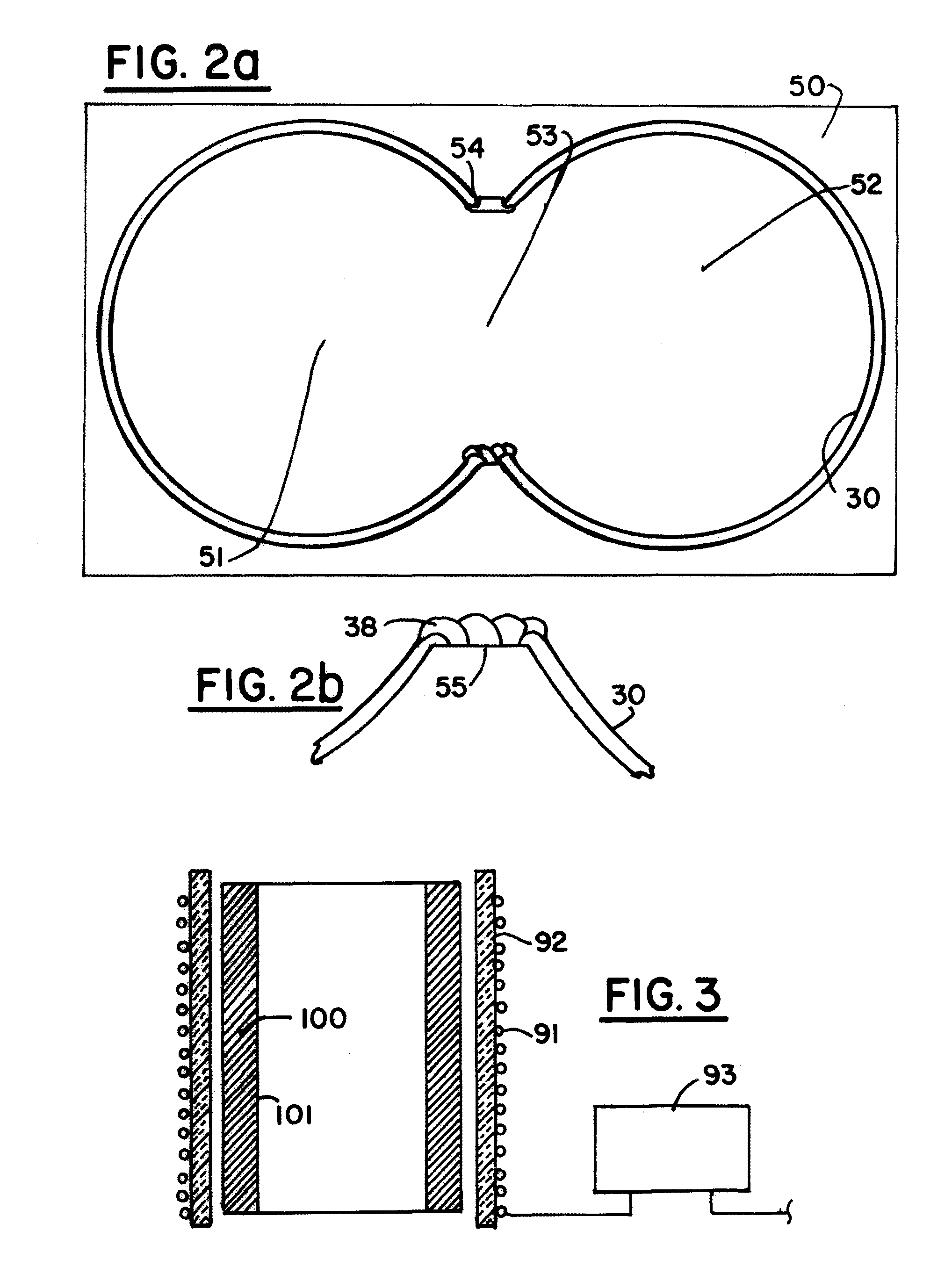
Further, the well-known difficulties of addressing multi-bore plasticating barrels still exist with the conventional systems.


