
Fiber optic cable and method of manufacture

Active Publication Date: 2012-04-26
CARLISLE INTERCONNECT TECH
View PDF11 Cites 47 Cited by
  • Summary
  • Abstract
  • Description
  • Claims
  • Application Information

AI Technical Summary

Benefits of technology

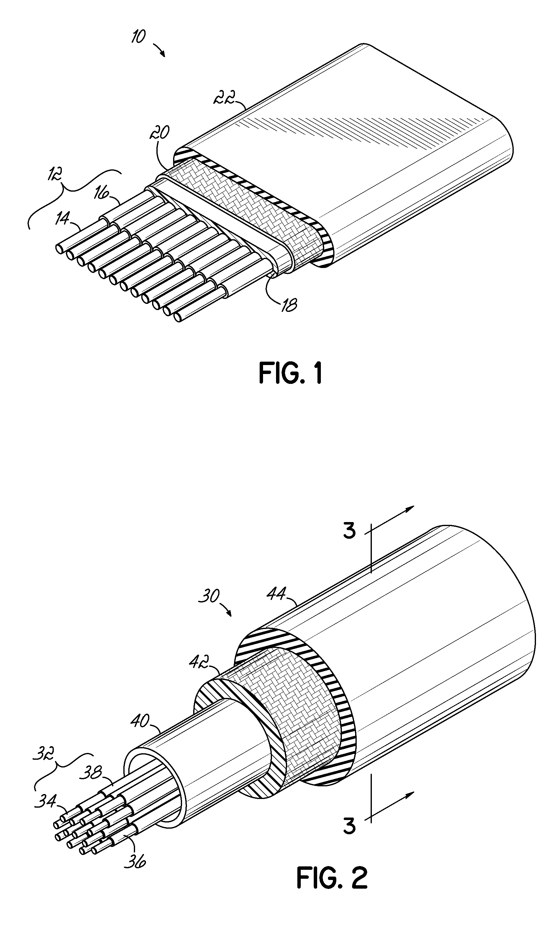
[0028]Invention advantageously provides a multi-strand optical cable in a round form factor that is highly tolerant of crushing, pinching and bending. Through a unique combination of materials and dimensions, the invention is able to operate over a broad operating temperature range, has low smoke and toxic gas production when exposed to flame, is highly crush and bend resistant, has a non-preferential bend axis, is resistant to chemicals, and is compatible with high density optic connectors and capable of high density optical packaging.
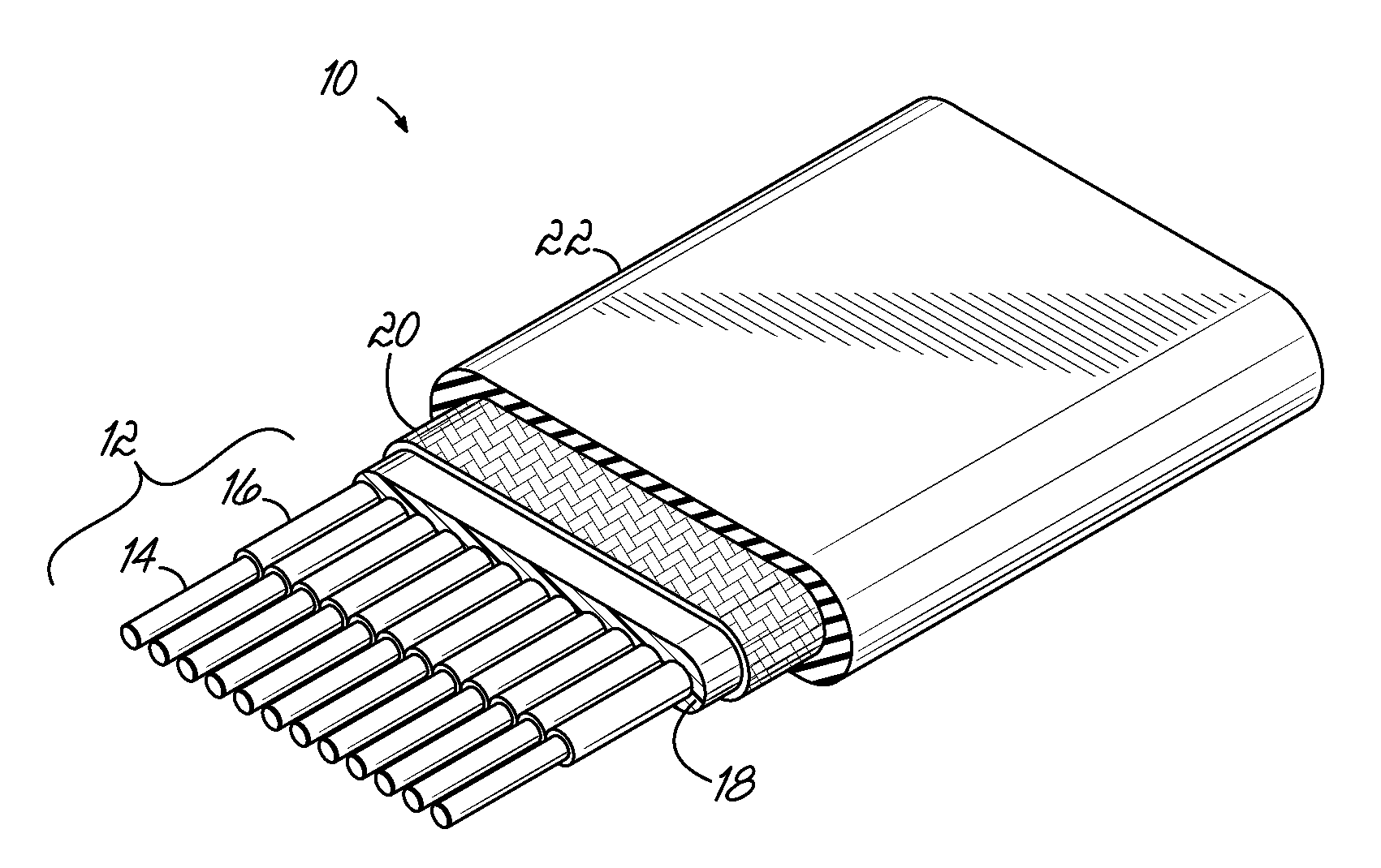
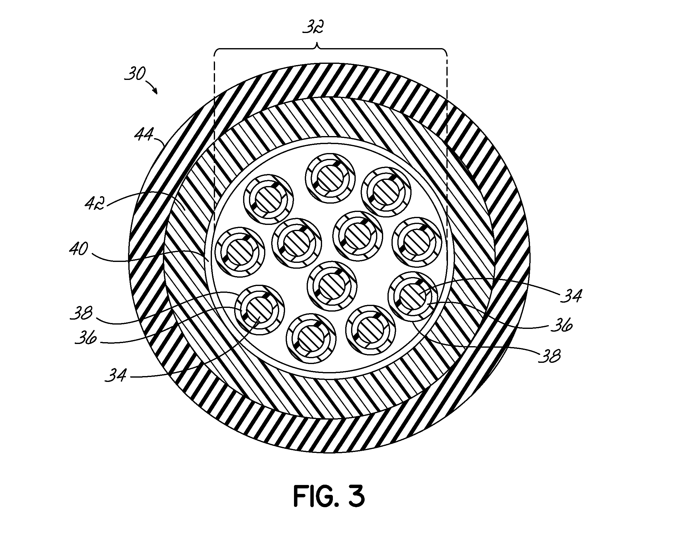
[0029]In one embodiment of the invention, the optic-fiber cable has a round buffer tube comprised of a fluoropolymer encapsulated by a round strength member layer comprised of aramid and glass fibers, and external jacket comprised of a fluoropolymer. The specific combination of layer thicknesses of the buffer tube, strength member, and cable jacket, as well as the ability of the fibers to float within the buffer, enable an embodiment of the invention to have unexpectedly increased resistance to damage of the optical fiber and cable by mechanical forces. The buffer tube is a loose buffer design that allows one or more fibers to float inside the fiber-optic cable so that the fibers are free to move relative to each other and the buffer, reducing susceptibility to performance degradation from pinching or kinking when the cable is subjected to tight bends or crushing forces, and allowing compatibility with ribbon connectors. The round configuration advantageously reduces cable size, improving ease of installation into tighter spaces and allowing the fiber-optic cable to pass thought smaller apertures than a ribbon cable containing a similar number of fiber-optic strands. The round design may also provide improved crush resistance and does not have a preferential bend axis as compared to a ribbon cable.

Problems solved by technology

Typically, the space within an aircraft is limited and thus the weight and size of cables running throughout an aircraft is always of utmost concern.
Furthermore, there are harsh conditions inherent in such operational and installation environments.
Still further, even minor failures in the fiber-optic cable can result in significant, undesirable consequences.
Installation within the confined spaces presented by an airframe can subject a fiber optic cable to tight bends, high pinching and crushing forces, as well as high pulling stresses as installers manipulate the cable.
Severe bending or forcing the cable around a small radius may result in a kink in the cable, which may result in reduced light transmission sufficient to render the cable inoperative.
These performance requirements may present conflicting design choices in providing suitable fiber-optic cables.
For example, a fiber-optic cable that is designed to withstand high crushing and pulling forces may be too thick to meet bend radius requirements or too difficult to install.
Designing fiber-optic cables for aerospace applications is further complicated by constraints on the choice of materials available that satisfy safety requirements, such as low production of smoke and toxic chemicals when subjected to fire.

Method used


Image

  • Fiber optic cable and method of manufacture
  • Fiber optic cable and method of manufacture
  • Fiber optic cable and method of manufacture

Examples


Embodiment Construction

[0031]The fiber-optic cable constructed in accordance with the aspects of the present invention provides a multiple fiber cable that has decreased susceptibility to crushing, pinching and other mechanical damage. Furthermore, the fiber-optic cable is configured in such a way that it tolerates high operating temperatures, produces low smoke and toxicity in the presence of fire, has a non-preferential bend axis, and is capable of use in high density optical packaging and fiber-optic connectors. Such design parameters are particularly important in aerospace applications where size and weight are critical factors and environmental conditions are harsh. In addition to meeting the design goals noted above, the present invention also provides improved bend / kink performance, so that the cable may be more vigorously implemented in tighter spaces. All of these various benefits are achieved as noted, without a degradation of the optical, mechanical or thermal performance the fiber-optic cable ...


PUM


Abstract

A fiber-optic cable for applications subject to extreme temperatures and high crushing and bending forces incorporating a loose fluoropolymer buffer material, a aramid / fiberglass strength member, and a fluoropolymer outer jacket compromising low smoke, low toxicity, and low flammability when exposed to flame.

Description

FIELD OF THE INVENTION[0001]The present invention relates generally to fiber optic cables and, more specifically, to a fiber optic cable having improved mechanical and optical performance characteristics.BACKGROUND OF THE INVENTION[0002]Optical fibers are used in an ever-increasing number of applications for transmitting data signals. An optical fiber is a thin transparent strand of material that acts as a waveguide for light. Optical fibers have several advantages over traditional copper conductors, including their light weight, high bandwidth, smaller size, immunity from electromagnetic interference, and low signal attenuation over long distances. Owing to these characteristics, optical fibers are particularly useful for providing a physical transmission medium for communications links and have replaced copper conductors in many communications applications. The small size, light weight and superior performance characteristics of optical fiber or “fiber-optic” cables also makes the...

Claims


Application Information

Patent Timeline
IPC IPC(8): G02B6/44G02B6/02
CPCG02B6/4432G02B6/4495G02B6/4436G02B6/4431
Inventor MESSER, MARK ALEXANDER
Owner CARLISLE INTERCONNECT TECH
Learn More