
Pipetting nozzle for autoanalyzer, method for producing same and autoanalyzer using same

a technology of pipetting nozzle and autoanalyzer, which is applied in the direction of instruments, nuclear engineering, laboratory glassware, etc., can solve the problems of inability to prepare large quantities, inability to analyze, and high cost of reagents, so as to reduce the amount of reagents, enhance the analytical reliability of the autoanalyzer, and inhibit the adsorption of biological polymers.

Inactive Publication Date: 2012-01-26
HITACHI HIGH-TECH CORP
View PDF3 Cites 1 Cited by
  • Summary
  • Abstract
  • Description
  • Claims
  • Application Information

AI Technical Summary

Benefits of technology

[0027]According to the present invention, it is possible to fabricate a pipetting nozzle onto a surface of which a polyethylene glycol derivative is chemisorbed and coated, and inhibit the adsorption of biological polymers, such as protein. Consequently, it is possible to reduce carry-over during dispensing operation, thereby enhancing the analytical reliability of an autoanalyzer. In addition, these advantages contribute to reductions in the amounts of samples and reagents used, and to a reduction in the running cost of the autoanalyzer.

Problems solved by technology

At this time, adverse effects may be caused on measurement results if constituents of a dispensed liquid remaining on surfaces of a pipetting nozzle get mixed in with the next dispensed liquid.
The problem of carry-over is deeply linked to the recent demand for reductions in the amounts of samples and reagents in the field of autoanalyzers.
In some cases, the sample itself is valuable, and therefore, cannot be prepared in large amounts.
In addition, reagents generally tend to be costly as the details of analysis become increasingly sophisticated.
It is difficult in some cases, however, to clean off biological polymers as typified by protein by using such a method.
However, the deactivated residues of samples accumulate on a nozzle surface in this method, and therefore, a pipetting nozzle cannot endure a long period of use (Patent Literature 3).
It is difficult, however, to form the disposable nozzle into a fine structure from the viewpoint of strength and machining accuracy.
In addition, use of disposable nozzles has the problem of producing massive amounts of waste and increasing environmental burdens.

Method used


Image

  • Pipetting nozzle for autoanalyzer, method for producing same and autoanalyzer using same
  • Pipetting nozzle for autoanalyzer, method for producing same and autoanalyzer using same
  • Pipetting nozzle for autoanalyzer, method for producing same and autoanalyzer using same

Examples


experimental example

[0037]First, in order to enhance the reliability of analysis, a planar substrate was used to verify effectiveness. The size of the substrate used was 10 mm×10 mm×0.5 mm, and a 10 mm×10 mm surface was used as a measuring surface for effectiveness verification.

[0038](Fabrication of Substrate to which Polyethylene Glycol Derivative is Adsorbed)

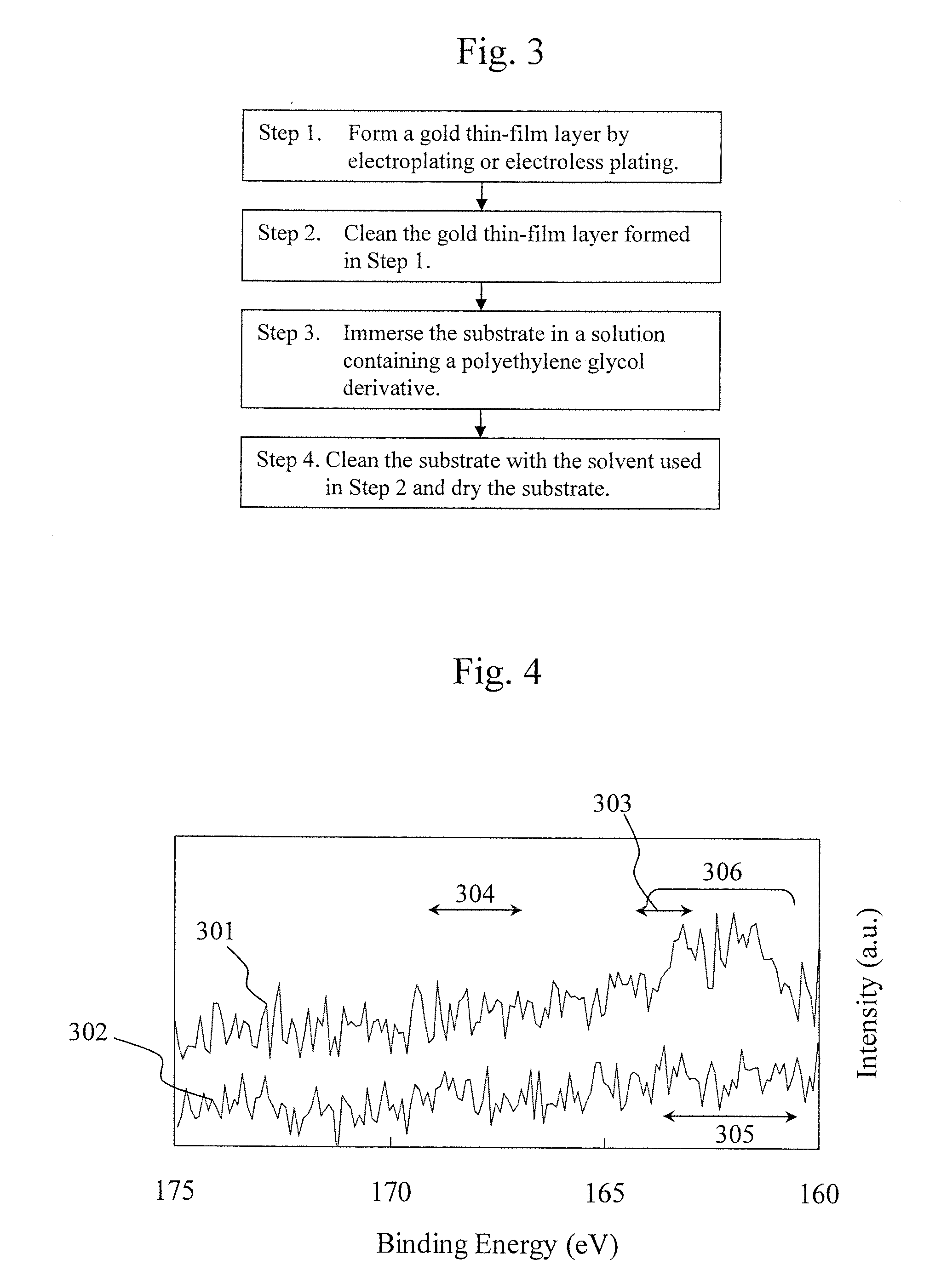
[0039]FIG. 3 shows a process flow of an experiment.

[0040]Step 1. Form a gold thin-film layer by electroplating or electroless plating.

[0041]Specifically, electrolytic gold plating was performed on a stainless steel substrate. First, in order to remove grease remaining on stainless-steel surfaces, the surfaces were degreased with an alkaline solvent. Subsequently, the stainless-steel substrate was immersed in an acidic activation bath to activate substrate surfaces. A solution composed of potassium gold cyanide, cobalt sulfate, and citric acid monohydrate was used as a plating solution to perform gold plating. Treatment time, solution temperature,...

embodiment 1

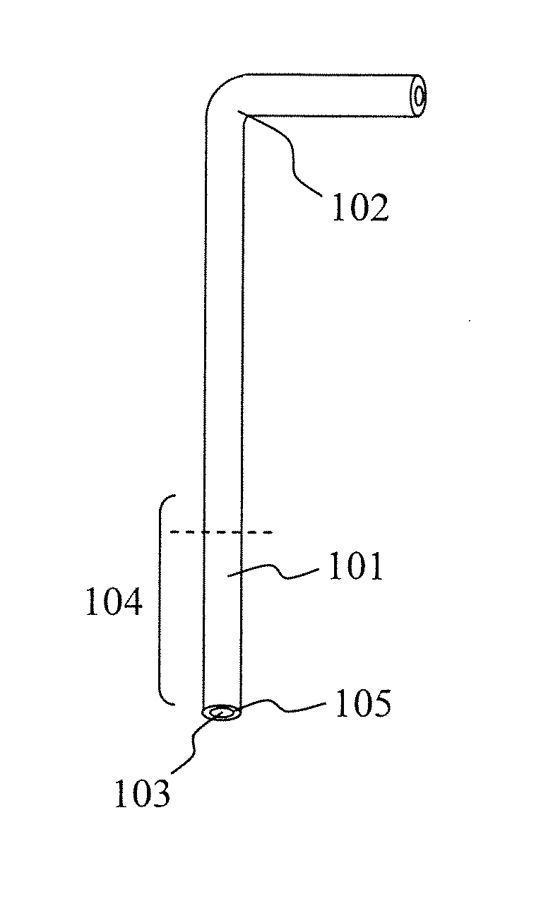
[0067]In the present embodiment, a description will be given of a case in which the same treatment as that in the experimental example is performed on a pipetting nozzle. First, a gold thin-film layer was formed on a surface of a stainless-steel pipetting nozzle in the same way as in the experimental example. Areas to be treated were specified as the edge portion 105 of the pipetting nozzle illustrated in FIG. 1 and the nozzle's area 104 to be immersed in a sample. In the present embodiment, the outer diameter of the treated nozzle tip was 0.5 mm and the inner diameter thereof was 0.3 mm. A gold thin-film layer was formed by electroplating across a 10 mm area of the nozzle tip. It is also possible to treat the entire surface of the pipetting nozzle. By limiting the areas to be treated to portions to be immersed, however, costs can be reduced.

[0068]Next, a surface on which the gold thin-film layer was formed by electroplating was ultrasonic-cleaned with ethanol for 15 minutes. At thi...

embodiment 2

[0071]FIG. 7 is a drawing illustrating a configuration example of an autoanalyzer according to the present invention. The basic operation of the autoanalyzer will be described next. One or more sample containers 25 are disposed in a sample storage mechanism 1. Here, a description will be given by taking as an example a sample disk mechanism which is a sample storage mechanism mounted on a disk-like mechanism. Alternatively, the sample storage mechanism may be in other forms, for example, in the form of a sample rack or a sample holder commonly used in autoanalyzers. In addition, the term “sample” as referred to herein refers to a solution under test to be used for reaction in a reaction container. The sample may be a concentrate solution of a collected sample, or a solution prepared by applying processing treatment, such as dilution or pretreatment, to the concentrate solution. A sample in a sample container 25 is taken up by a sample pipetting nozzle 27 of a pipetting mechanism for...


PUM

PropertyMeasurementUnit
Molecular weightaaaaaaaaaa
Electrical conductoraaaaaaaaaa
Areaaaaaaaaaaa

Abstract

In an autoanalyzer for analyzing samples, such as urine and blood, analytical and measured values are prevented from being affected by carry-over caused by the repeated use of a pipetting nozzle. A molecular layer for inhibiting the adsorption of biological polymers is formed by coating surfaces of the pipetting nozzle with a polyethylene glycol derivative chemisorbed thereto, thereby reducing carry-over caused by the pipetting nozzle.

Description

TECHNICAL FIELD [0001]The present invention relates to a pipetting nozzle for autoanalyzers, a method for manufacturing the pipetting nozzle, and an autoanalyzer equipped with the pipetting nozzle.BACKGROUND ART [0002]In a clinical examination for medical diagnosis, biochemical analysis and immunological analysis are performed on protein, sugar, lipid, enzyme, hormone, inorganic ions, disease markers, and the like in a biological sample, such as blood and urine. Since a plurality of inspection items needs to be processed with high reliability and at high speed in a clinical examination, most of the items are processed using an autoanalyzer. As the autoanalyzer, there has been known, for example, a biochemical autoanalyzer in which a reaction liquid prepared by mixing a desired reagent into a sample, such as blood serum, and reacting the reagent with the sample is used as an object of analysis to conduct biochemical analysis by measuring the absorbance of the reaction liquid. This ty...

Claims


Application Information

Patent Timeline
IPC IPC(8): G01N30/00C25D3/48C25D5/48B05D3/06
CPCB01L3/0275B01L2200/141G01N35/1004B01L2300/161B01L2300/163B01L2300/0645
Inventor NOJIMA, AKIHIROTANIGUCHI, SHINICHIINOUE, TAKASHIISHIZAWA, HIROAKI
Owner HITACHI HIGH-TECH CORP
Learn More