Eureka AIR delivers breakthrough ideas for toughest innovation challenges, trusted by R&D personnel around the world.

Duty correcting circuit, delay-locked loop circuit and method of correcting duty

a duty correcting and delay-locked loop technology, applied in pulse manipulation, pulse duration/width modulation, pulse technique, etc., can solve the problems of small chip size and relatively small power consumption of the circuit including the duty correcting circuit, and achieve the effect of small chip size and small power consumption

Active Publication Date: 2011-12-08
SAMSUNG ELECTRONICS CO LTD
View PDF3 Cites 15 Cited by
  • Summary
  • Abstract
  • Description
  • Claims
  • Application Information

AI Technical Summary

Benefits of technology

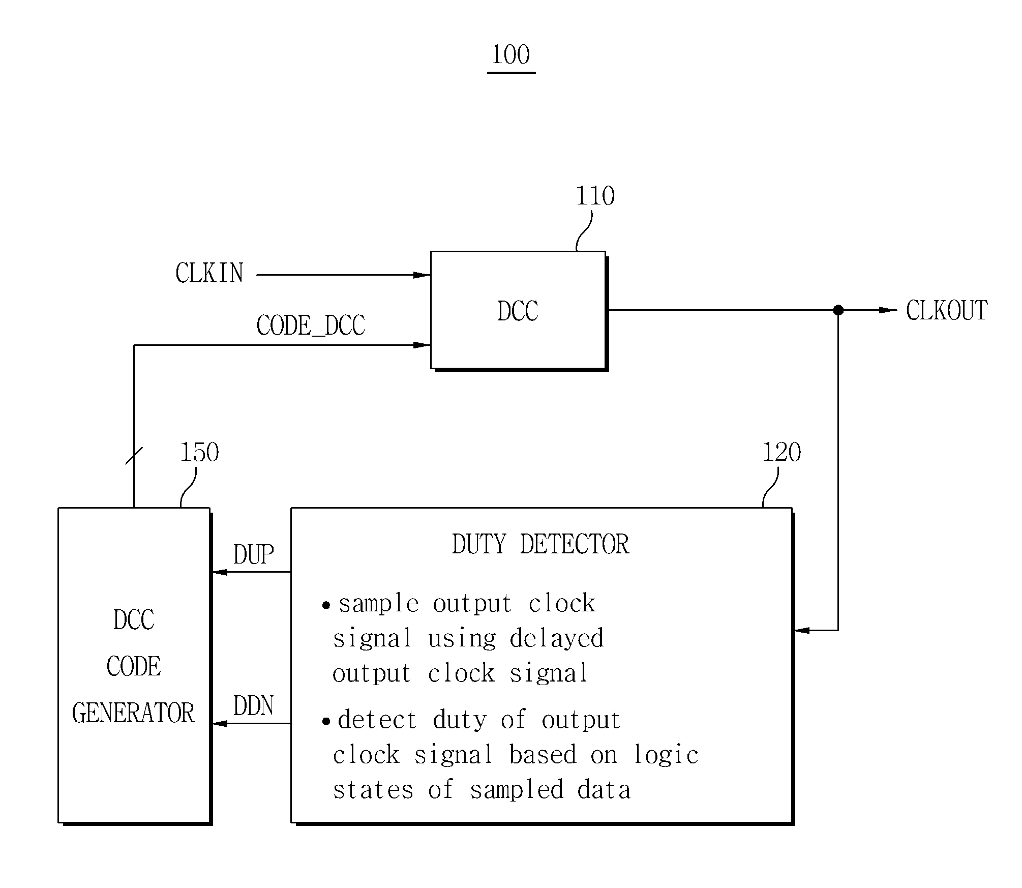
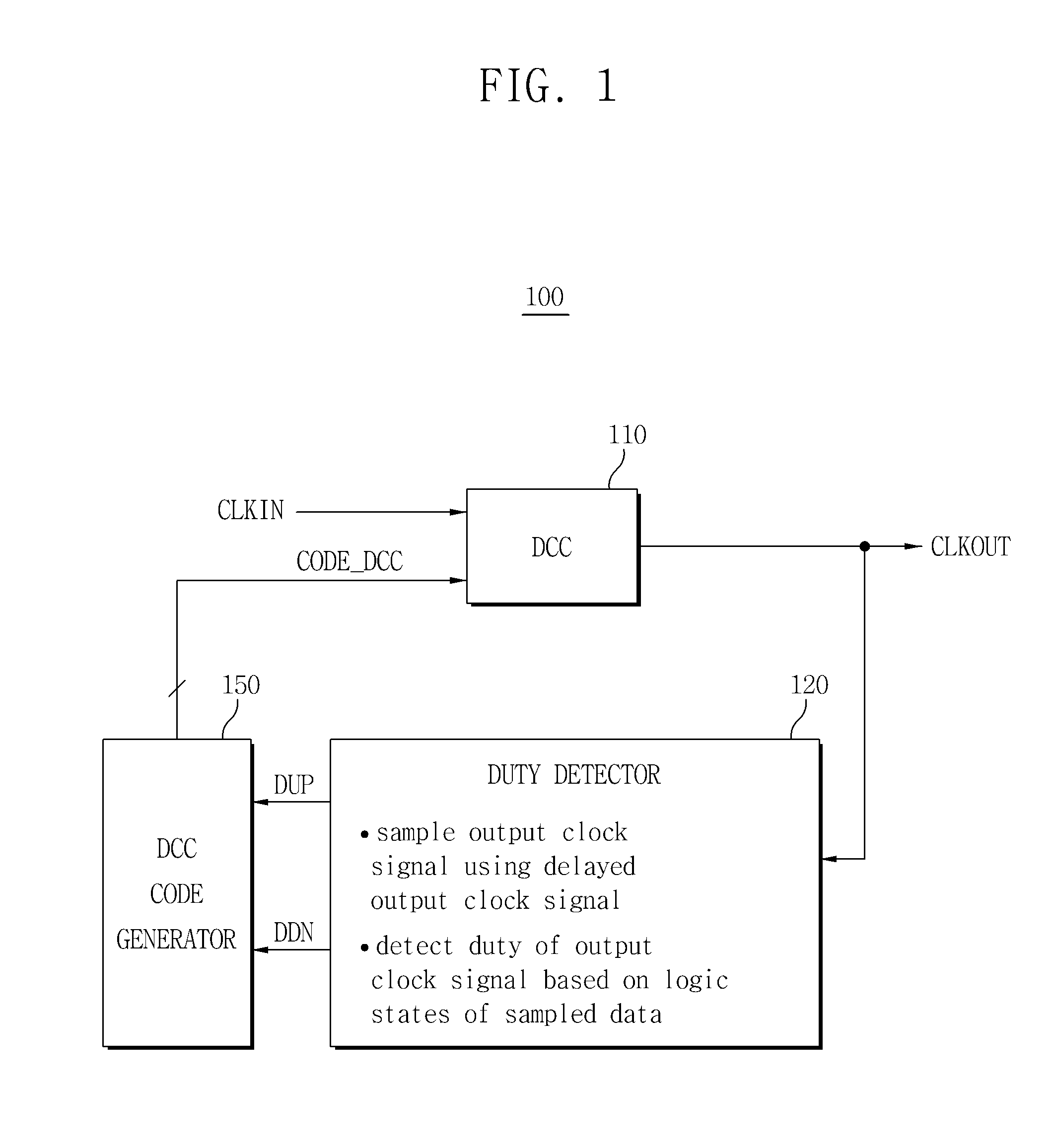
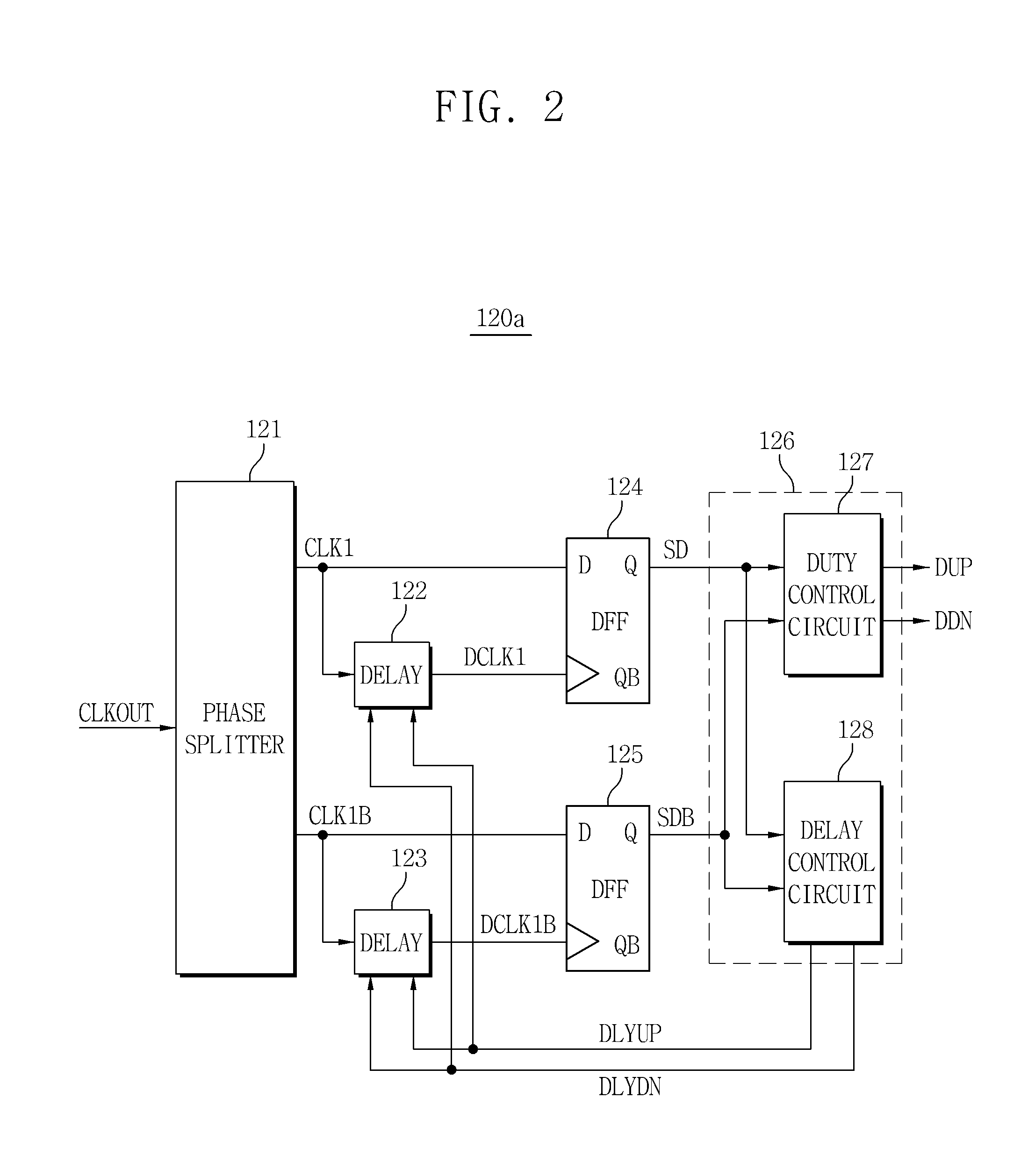
The patent text describes a duty correcting circuit that can detect and correct the duty cycle of an input clock signal in a digital mode with high precision. The circuit includes a duty detector that adjusts the delay time of the output clock signal based on the logic states of the first and second sample data to generate the duty-up and duty-down signals. The duty detector can detect the duty of the output clock signal and generate the duty-up and duty-down signals based on the logic states of the first and second sample data. The technical effect of this invention is to provide a precise and efficient method for detecting and correcting the duty cycle of an input clock signal in a digital system.

Problems solved by technology

The semiconductor device including the duty correcting circuit may have relatively small power consumption and a small chip size.

Method used


Image

  • Duty correcting circuit, delay-locked loop circuit and method of correcting duty
  • Duty correcting circuit, delay-locked loop circuit and method of correcting duty
  • Duty correcting circuit, delay-locked loop circuit and method of correcting duty

Examples


Embodiment Construction

[0057]Example embodiments will now be described more fully with reference to the accompanying drawings, in which example embodiments are shown. Example embodiments may, however, be embodied in many different forms and should not be construed as being limited to the embodiments set forth herein; rather, these embodiments are provided so that this disclosure will be thorough and complete, and will fully convey the concept of example embodiments to those of ordinary skill in the art. In the drawings, the thicknesses of layers and regions are exaggerated for clarity. Like reference numerals in the drawings denote like elements, and thus their description will be omitted.

[0058]It will be understood that, although the terms first, second, etc. may be used herein to describe various elements, components, regions, layers and / or sections, these elements, components, regions, layers and / or sections should not be limited by these terms. These terms are only used to distinguish one element, com...


PUM


Abstract

The duty correcting circuit includes a duty cycle corrector, a duty detector and a duty correction code generator. The duty cycle corrector corrects a duty cycle of an input clock signal to generate an output clock signal. The duty detector adjusts a delay time of the output clock signal to generate a sampling clock signal, samples the output clock signal in response to the sampling clock signal to generate sample data, and detects a duty of the output clock signal based on logic states of the sample data. Therefore, the duty correcting circuit precisely detects and corrects a duty of the output clock signal.

Description

CROSS-REFERENCE TO RELATED APPLICATION[0001]This application claims priority under 35 U.S.C. §119 to Korean Patent Application No. 10-2010-0053377 filed on Jun. 7, 2010 and Korean Patent Application No. 10-2010-0089654 filed on Sep. 13, 2010, in the Korean Intellectual Property Office (KIPO), the entire contents of which are hereby incorporated by reference.BACKGROUND[0002]1. Field[0003]Example embodiments of inventive concepts relate to a duty correcting circuit, and more particularly to a duty correcting circuit including a charge pump circuit and a method of correcting a duty.[0004]2. Description of Related Art[0005]Logic circuits of a semiconductor device, particularly, a semiconductor memory device, may operate in response to clock signals. An internal clock signal having a corrected duty and synchronized with an external input clock signal in consideration of a clock transmission path is needed so that an internal circuit having various functions can operate in response to the...

Claims


Application Information

Patent Timeline
Patent Type & Authority Applications(United States)
IPC IPC(8): H03K3/017
CPCH03K5/1565
Inventor NA, TAE-SIKKIM, JUN-BAE
Owner SAMSUNG ELECTRONICS CO LTD
Why Eureka
Eureka Blog
Learn More