Electrocatalyst Composition And Fuel Cell Containing Same

a technology of electrochemical composition and fuel cell, which is applied in the direction of cell components, carbon-silicon compound conductors, electrochemical generators, etc., can solve the problems of loss of electrochemical activity, severe retardation of platinum catalyst reaction kinetics, and cost of electrochemical reactions of platinum metal, etc., to achieve the effect of high efficiency, low cost and high efficiency

Inactive Publication Date: 2011-10-06
SWIFT ENTERPRISES
View PDF2 Cites 5 Cited by
  • Summary
  • Abstract
  • Description
  • Claims
  • Application Information

AI Technical Summary

Benefits of technology

[0021]The present inventors recognized a need for electrodes that retain acceptable electrocatalytic activity, while providing abundant, inexpensive, and efficient electrocatalytic materials which are alternatives to pure Pt catalysts. Accordingly, the present inventors carried out extensive research and unexpectedly discovered a new and improved fuel cell electrocatalyst composition designed to overcome the above-described problems and which can be used effectively in a fuel cell.
[0025]In a preferred embodiment, the electrocatalyst composition of the present invention can be effectively used in a direct hydrogen peroxide fuel cell. In such a case it is preferred that the fuel is in contact with the anode and that the fuel is comprised of one or more of sodium borohydride, ammonia, azide, ethanol or methanol, guanidine, urea and lithium borohydride.

Problems solved by technology

It has been found that these platinum catalysts are severely retarded in their reaction kinetics by carbon monoxide concentrations of only a few parts per million.
One major obstacle to the development of platinum containing catalytic electrodes for electrochemical reactions is the cost of the platinum metal.
Another major obstacle is the loss of electrochemical activity due to poisoning of the catalyst by carbon monoxide.
Various unsuccessful attempts have been made to find a solution to the CO poisoning problem; however, results have been proven to be too expensive, insufficiently effective or too impractical to be commercially viable.
However, the costs associated with these materials are still prohibitive for full exploitation in fuel cell technology.
Despite the extensive research that has been carried out in this area, the detailed mechanism of the oxygen reduction reaction ORR, even at Pt, is still uncertain.
The foregoing problems have been recognized for many years and while numerous solutions have been proposed, none of them adequately address all of the problems in a single device.
The above conventional electrocatalyst materials, however, experience various drawbacks, such as CO poisoning.

Method used


Image

  • Electrocatalyst Composition And Fuel Cell Containing Same
  • Electrocatalyst Composition And Fuel Cell Containing Same
  • Electrocatalyst Composition And Fuel Cell Containing Same

Examples


example 1

4 by 4 Inch Fuel Cell

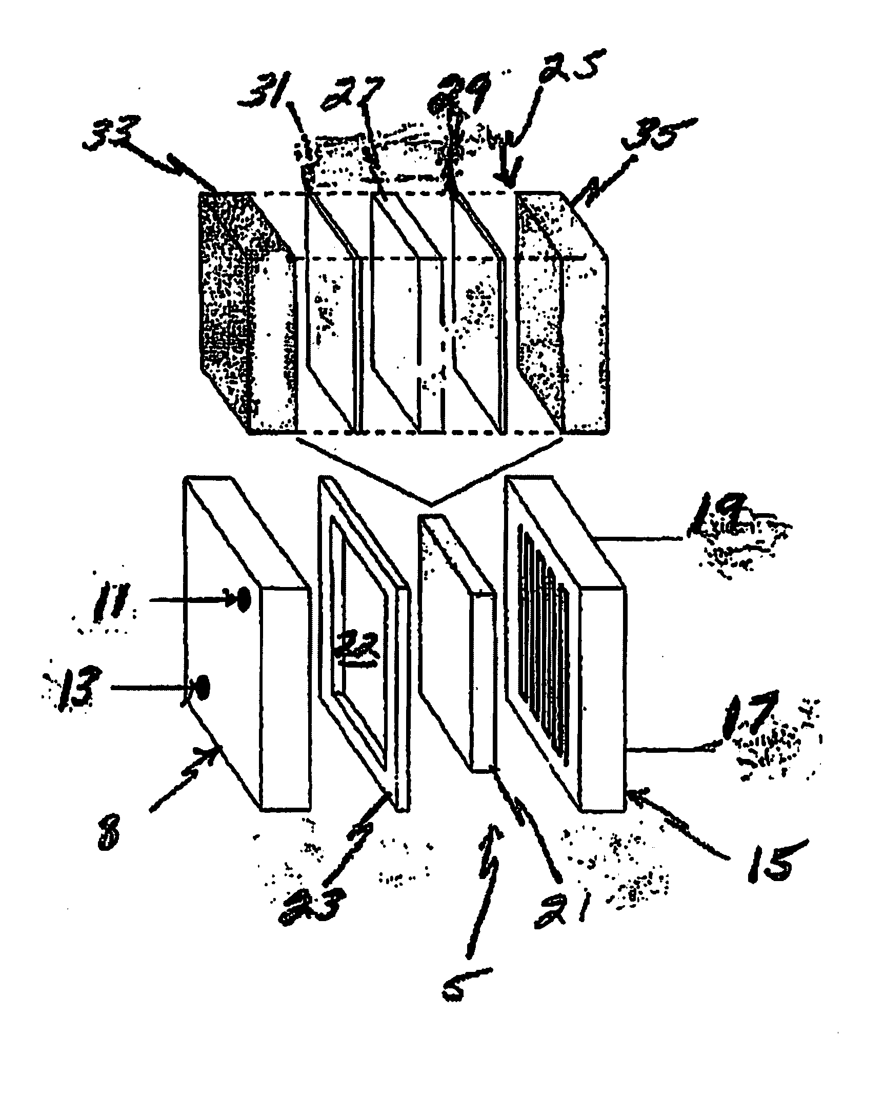
[0082]A 4.0 inch by 4.0 inch fuel cell was constructed with a cathode opposite an anode, and a membrane electrode assembly disposed between the cathode and anode. The cathode and anode are made up of graphite plates approximately one-inch thick with a machined serpentine flow path on one side of the plate.

[0083]The fuel cell membrane electrode assembly was composed of a first current collector with a second current collector disposed opposite the first, both being made from a porous carbon paper having a thickness of 0.005 inch, and a proton transfer membrane 0.002 inch thick NAFION® was disposed between the first and second current collectors. An electrocatalyst layer ranging in thickness between 0.0005 and 0.002 inches was disposed on the current collector and adjacent to the proton transfer membrane.

[0084]This electrocatalyst layer was comprised of electrically conductive particles in a mixture of carbon black, activated carbon, and graphite. The catalysts we...

example 2

3 by 6.5 Inch Fuel Cell Stack

[0088]A 3.0 inch by 6.5 inch fuel cell was constructed with a cathode opposite an anode, and a membrane electrode assembly disposed between the cathode and anode. Twelve (12) of these cells were positioned back to back to make up an entire fuel cell stack. The cathode and anode were made of graphite plates approximately 0.25 inches in thickness with a machined serpentine flow path on one side of the plate.

[0089]The fuel cell membrane electrode assembly was comprised of a first current collector with a second current collector disposed opposite the first, both being made from a porous carbon paper with a 0.005 inch thickness, and a proton transfer membrane 0.002 inch thick NAFION® was disposed between the first and second current collectors. An electrocatalyst layer between 0.0005 and 0.002 inches in thickness was disposed on the current collector adjacent to the proton transfer membrane.

[0090]This electrocatalyst layer was comprised of electrically condu...

example 3

3 by 6.5 Inch Fuel Cell Stack

[0095]A 3.0 by 6.5 inch fuel cell was constructed with a cathode opposite an anode, and a membrane electrode assembly disposed between the cathode and anode. Twelve (12) of these cells were positioned back to back, anode side to cathode side, to form an entire fuel cell stack. The cathode and anode were made of graphite plates approximately 0.25 inches thick with a machined serpentine flow path on one side of the plate.

[0096]The fuel cell membrane electrode assembly was comprised of a first current collector with a second current collector disposed opposite the first, both being made from a porous carbon paper having a thickness of 0.005 inches, and a proton transfer membrane of 0.002 inch thick NAFION® was disposed between the first and second current collectors. An electrocatalyst layer ranging between 0.0005 and 0.002 inches thick was disposed on the current collector and adjacent to the proton transfer membrane.

[0097]This electrocatalyst layer was co...


PUM


Abstract

An electrocatalyst composition comprising one or more electrically conductive particles of one or more of carbon black, activated carbon, and graphite with one or more catalysts of a macrocycle and a metal adhered and / or bonded to the outer surface of the particles. The catalyst can be comprised, for example, of one or more of acetylacetonate and phthalocyanine and a metal. The metal component used in the electrocatalyst composition is comprised of one or more of iron, nickel, zinc, scandium, titanium, vanadium, chromium, copper, platinum, ruthenium, rhodium, palladium, silver, osmium, iridum, platinum and gold. An ionic transfer membrane having a layer of the electrocatalyst thereon is disposed in a fuel cell in communication with and between current collectors.

Description

REFERENCE TO A RELATED APPLICATION [0001]This International Application claims the benefit of U.S. Provisional Application No. 61 / 237,550, filed Aug. 27, 2009, the contents of which are incorporated herein by reference.BACKGROUND OF THE INVENTION[0002]1. Field Of The Invention[0003]The present invention relates generally to an electrocatalyst composition such as electrocatalyst powders used in the fabrication of energy devices such as fuel cells, and more particularly, to fuel cells containing the improved electrocatalyst compositions of the present invention.[0004]2. Description Of Related Art[0005]A fuel cell is similar to other electrochemical cells in which there is an electrolyte (e.g., liquid or solid) and two electrodes (e.g., a cathode and an anode) at which the electrochemical reaction occurs. The fuel cell is distinguished from a conventional battery by its fuel storage capacity and the fact that the electrodes are catalytically active. The fuel cell is used to convert sto...

Claims


Application Information

Patent Timeline
IPC IPC(8): H01M4/90H01M8/10
CPCH01B1/04H01M4/9008Y02E60/50H01M2008/1095H01M4/9083
Inventor RUSEK, JOHN J.BOWER, DONALDMEYER, RICHARDDAROUX, MARK L.FANG, WANJUNG
Owner SWIFT ENTERPRISES
Why Eureka
Try Eureka