
Fluid light guide

Inactive Publication Date: 2003-03-06
ENTERPRISE DEV CORP
View PDF0 Cites 35 Cited by
  • Summary
  • Abstract
  • Description
  • Claims
  • Application Information

AI Technical Summary

Benefits of technology

[0016] It is another object of the present invention to provide an economically viable, large core light guide for remote, energy efficient lighting applications.
[0018] Still another object of the present invention is to provide a very low refractive index coating that can be applied in a continuous process to the inner surface of a low cost tube of substantial length to provide highly efficient and inexpensive waveguides.

Problems solved by technology

Unfortunately, quartz waveguides are very fragile as well as being very expensive and difficult to produce.
Although ideal for communications purposes, which require the transmission of low energy radiation over long distances, quartz fibers present great difficulties for the transmission of relatively large amounts of power over shorter distances.
Moreover, a principal problem with these fibers is that they must be very thin to provide required flexibility, which is a significant disadvantage when the fibers are fragile as in quartz.
In addition, the power densities created in thin fibers with laser applications can be high enough to cause breakdown of the core material.
In addition, it is very difficult to successfully launch broad light beams that may be 50 mm or more in diameter, or large diameter laser beams, into fibers of this type without high losses.
Some optical fibers of this type have been formed from finely drawn quartz capillary tubes filled with a liquid, but the same problems of fragility, alignment, and breakdown of the material generally prevent their use in any of the aforementioned applications requiring high power levels.
However, with use the individual fibers begin to fracture, leading to increasing numbers of dead spots and decreasing efficiency of the bundle.
This results in initial losses proportional to the non-transmitting area of the bundle, and if the energy of the incident light beam is high enough, destruction of the bundle due to energy absorption.
Thus, waveguides of this type cannot usually be used in the transmission of high energy radiation.
However, because of the nature of the materials from which they are constructed, they tend to have high light losses, can generally operate only at low temperatures and are generally suitable only for non-critical, low light applications.
The main problem with these large diameter, liquid core fibers is the availability of low refractive index cladding and high refractive index, low loss core materials.
Put another way, the problem is to find workable combinations of solid cladding and fluid core materials such that the refractive index differential provides an acceptable numerical aperture for the resultant fiber.
These materials are relatively expensive and require exacting manufacturing techniques and standards.
However, the materials currently available are expensive or suffer from limited light transmission or wavelength range performance.
Moreover, the coating procedures during manufacturing are batch processes which are very cumbersome for making such waveguides in substantial lengths such as 50-100 feet or more.
However, the '742 patent is typical in that it requires supercritical processing to prepare aerogel films.
This would be very difficult to implement commercially in that the process must somehow coat the fiber, maintain it in a wet state, transfer it to an autoclave and then supercritically extract it.
By contrast, fiber light guides made from solid material such as plastic, glass or silica as discussed above, are generally limited to small diameters to maintain flexibility and must be bundled in order to transmit large amounts of light.
The result of this latter choice makes for a flexible but inefficient and relatively expensive light guide.
However, the most preferred fluid is a water / aqueous system due to the fact that silicone oils, alcohols, and the like can wet the aerogel film under certain circumstances and possibly destroy the wave guiding behavior.
While the aerogel structure can be stressed, its performance under tension is generally of concern because it is inherently very brittle.
Otherwise, an unacceptable increase in the refractive index of the cladding will occur, thereby losing the benefit of having the aerogel film in the first place since the differential in refractive indices between cladding and core will have been reduced.

Method used


Image

  • Fluid light guide
  • Fluid light guide
  • Fluid light guide

Examples


example ii

[0049] In a test similar to the above Example I, test films were prepared using the ambient temperature / pressure aerogel process that exploits reversible drying shrinkage. A silica gel was derivatized with hexamethyldisilazane, diluted with solvent and liquefied by ultrasound. The sol was then re-concentrated and dip coated onto a silicon substrate. Films were either dried at 100.degree. C. for five hours in nitrogen (film HMDS -100) or pyrolyzed to 450.degree. C. in nitrogen (film HMDS -450). The HMDS-100 film was measured first in air using a spectroscopic ellipsometer. The measurement results were a thickness of 761 nm and a refractive index of 1.07. The film was then put in water in the cell with the incident angle for the ellipsometer being 75.degree., and a total reflection was obtained. Fitting of the ellipsometric parameters gave a refractive index of only 1.09 for the film. Since the refractive index of water is 1.33, the critical angle for total reflection is 90.degree. -s...

example iii

[0051] The refractive index of the deposited coating 20 of the invention may be tailored to a preferred range of 1.1 to 1.2 by utilizing several parameters. These included varying the extent of derivatization of the siloxane polymers in the sol with organosilyl ligands, generally R.sub.3Si-, where R is methyl, ethyl, propyl, phenyl, fluoroalkyl and the like. The refractive index may also be tailored by the size and extent of condensation of the siloxane polymers and the nature of the R group. In preferred form, the optimum synthesis and processing variables achieve a refractive index of 1.12 combined with an acceptance angle of greater than 90.degree..

example iv

[0052] The present invention is directed to producing an interiorly coated tube to be used in the creation of a liquid or gel core light guide with low loss performance on the order of about 50% loss / 100 feet initially over the whole visible region of the electromagnetic radiation spectrum, and ultimately extending into the UV and IR regions of the spectrum. The tube of the invention is mechanically robust and resistant to deformation and abuse. The film 20 performs under normal wear and tear when the waveguide is bent, twisted and subjected to constant movement. In particular, silica aerogel layered on the inside surface of a polyethylene tube yielded significant results.


PUM

PropertyMeasurementUnit
Fractionaaaaaaaaaa
Fractionaaaaaaaaaa
Porosityaaaaaaaaaa

Abstract

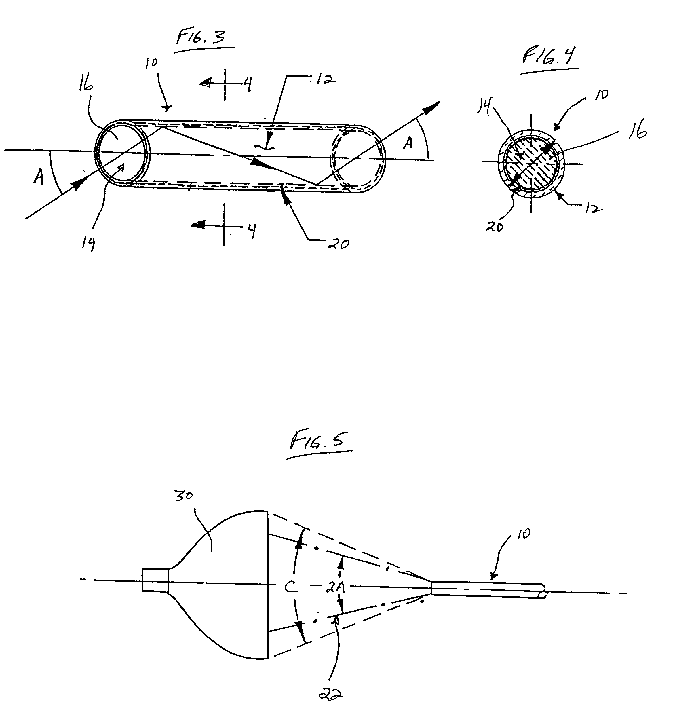
A light guide is disclosed and includes a flexible elongated tube having an inner surface and first and second ends. A non-supercritically dried hydrophobic aerogel film is affixed to the inner surface of the tube as a cladding layer, and a fluid core is disposed within the tube. The fluid core has a refractive index greater than the refractive index of the aerogel cladding film.

Description

[0001] This is a continuation-in-part of pending U.S. patent application Ser. No. 09 / 132,710, filed Aug. 12, 1998, the contents of which are specifically incorporated herein by reference.[0002] 1. Field of the Invention[0003] The present invention relates generally to optical waveguides and, more particularly, to fluid light guides for the transmission of a wide range of wavelengths. Specifically, the present invention relates to liquid / gel light guides having a high critical angle of acceptance for illumination purposes and a continuous process for the manufacture thereof.[0004] 2. Description of the Prior Art[0005] Numerous kinds of waveguides or optical fiber structures have been developed for the transmission of electromagnetic radiation of various wavelengths between infrared to ultraviolet, and in particular in the visible light region. These fiber-optic devices are utilized in numerous industries, in particular the medical, communication and lighting industries, for a number ...

Claims


Application Information

Patent Timeline
IPC IPC(8): G02B1/04G02B6/032
CPCG02B1/048G02B6/032
Inventor FRAVAL, HANAFI R.BRINKER, C. JEFFREY
Owner ENTERPRISE DEV CORP
Learn More