Cushioning pads and the formation of cushioning pads

Inactive Publication Date: 2006-03-07
PHOENIX PERFORMANCE PRODS
View PDF3 Cites 41 Cited by
  • Summary
  • Abstract
  • Description
  • Claims
  • Application Information

AI Technical Summary

Benefits of technology

[0015]It is an object of the present invention to provide an efficient and inexpensive method of making a comfortable cushioning pad.

Problems solved by technology

Such open-air material constructions of impact absorbing pads suffer drawbacks.
One drawback is that the impact absorption ability of the pad is directly related to its thickness.
On the other hand, if the resilient layer is made too thin, the impact absorbing pad will offer insufficient cushioning.
Another drawback is that an uncovered, resilient layer tends to be slow in re-adopting its original shape after being compressed.
This is not acceptable in applications like sporting gear.
If the impact absorbing pad is still compressed, or only beginning to re-adopt its original shape, when a next succeeding impact occurs, the wearer of the impact absorbing pad may suffer injury due to insufficient impact absorption.
Therefore, these well-known open-air types of impact absorbing pads are unsuitable as protective gear in sports.
Gel-packs also suffer drawbacks.
The relatively denser gel does not offer the comfort associated with the air cushioning of an open-air material.
Also, gel-packs are constructed of relatively more heavy and expensive materials.
The failure has been attributed to the lack of knowledge of the inventor's method of production.

Method used


Image

  • Cushioning pads and the formation of cushioning pads
  • Cushioning pads and the formation of cushioning pads
  • Cushioning pads and the formation of cushioning pads

Examples


Embodiment Construction

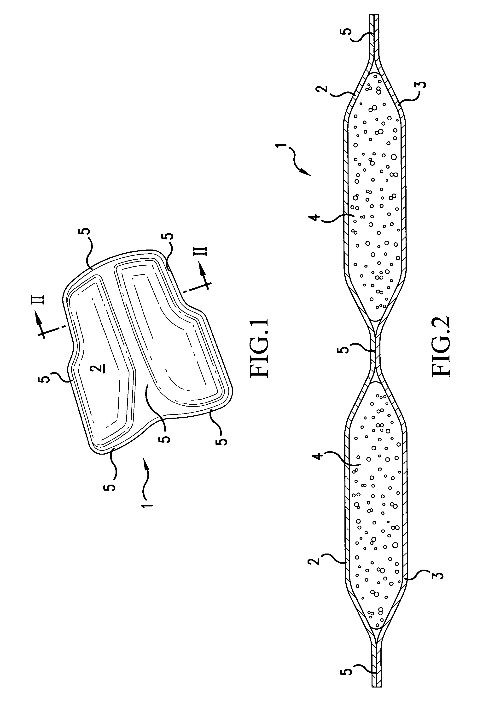
[0030]FIGS. 1 and 2 illustrate a pad 1 constructed by a method in accordance with the present invention. The pad 1 includes a first layer 2 of a first material and a second layer 3 of a second material. The first layer 2 is attached to the second layer 3 at seamed sections 5 to encapsulate one or more components 4.

[0031]The first and second materials are preferably a flexible resilient material which has a low permeability to air, such as a closed-cell foam, like polyethylene foam. The third material is preferably a flexible resilient material which can absorb and release air, such as an open-celled, foam like polyurethane foam. Such open-cell foam typically contains approximately 80% air by volume when in an uncompressed state.

[0032]FIG. 3 is a cross sectional view illustrating an apparatus for, and a method of, forming the pad 1 of FIGS. 1 and 2. The apparatus includes a first feeding spool 10 having a first web 12 of material wound thereon and a second feeding spool 11 with a sec...


PUM

PropertyMeasurementUnit
Pressureaaaaaaaaaa
Sizeaaaaaaaaaa
Adhesivityaaaaaaaaaa

Abstract

A method of forming a cushioning pad includes placing a component formed of polyurethane foam onto a first web of polyethylene foam. A second web of polyethylene foam is then placed over the component to sandwich the component. Heat and pressure is applied to the sandwich, which flattens the component and forms a seam between the first web and the second web encircling the component. If an unsealed cushioning pad is to be formed, a hollow needle is inserted into one of the first web or the second web. Air passes through the hollow needle and into the component, which absorbs the air and expands. Later, the needle is removed. If a sealed cushioning pad is to be formed, an insertion point of the hollow needle is in the seam, between the first web and the second web. After the component absorbs air and expands, the needle is removed and the insertion point of the hollow needle is re-seamed.

Description

[0001]This is a continuation of application Ser. No. 09 / 335,987, filed Jun. 18, 1999, now abandoned, the entire contents of which are hereby incorporated by reference.BACKGROUND OF THE INVENTION[0002]1. Field of the Invention[0003]The present invention relates to a method of forming a cushioning pad, and several cushioning pads produced by the method.[0004]2. Description of the Related Art[0005]Cushioning pads, or impact absorbing pads, are well known in the existing art. Impact absorbing pads are used to improve the comfort and ergonomics of many items which interact with humans and animals. Also, impact absorbing pads are useful in dampening vibrations and deadening sound between interacting objects. Typical applications for these pads include sporting gear apparel, seat covers, and shoe insoles and linings.[0006]Typical impact absorbing pads are constructed of a resilient layer of an open-air material, such as foam or polyurethane. The resilient layer is porous and naturally hold...

Claims


Application Information

Patent Timeline
IPC IPC(8): B68G7/00B29C43/24B29C43/30B29D99/00
CPCB29C43/222B29D99/0092B29C43/305Y10T428/23B29C43/46B29C2043/189B29K2075/00B29K2105/04B29K2105/251Y10T156/1028Y10T156/103Y10T428/233Y10T29/481Y10T428/239Y10T156/1052Y10T29/49829
Inventor CUDNEY, DOUGLAS J.BREITBACH, KAREN
Owner PHOENIX PERFORMANCE PRODS
Why Eureka
Try Eureka