
Gas barrier film manufacturing method

a technology of gas barrier film and manufacturing method, which is applied in the direction of plasma technique, metal material coating process, coating, etc., can solve the problems of low heat resistance of inexpensive resin film, increased apparatus cost, and insufficient flexibility of the layer, so as to achieve excellent gas barrier property, low heat resistance, and high quality

Inactive Publication Date: 2011-08-11
FUJIFILM CORP
View PDF10 Cites 5 Cited by
  • Summary
  • Abstract
  • Description
  • Claims
  • Application Information

AI Technical Summary

Benefits of technology

[0010]In addition, a deposition pressure of 10 Pa requires a high-performance deposition apparatus, which extremely raise the apparatus costs especially if the productivity is to be improved, that is to say, the flow rate of a gaseous raw material is to be enhanced.
[0013]An object of the present invention is to solve the above problems with the prior art so as to provide a gas barrier film manufacturing method which makes it possible to use a resin film having a low resistance to heat, such as PET film, as a base film to manufacture a gas barrier film of high quality exhibiting an excellent gas barrier property and a high flexibility on an inexpensive apparatus with a high productivity.
[0018]According to the present invention with the configuration as described above, a resin film having a low resistance to heat, such as PET film, can be used as a base film to manufacture a gas barrier film of high quality exhibiting an excellent gas barrier property and a high flexibility, with the reduction in gas barrier property due to particles getting into the gas barrier layer of the film being suppressed significantly, on an inexpensive manufacturing apparatus, and with a high productivity as a result of employing a roll-to-roll method or the like.

Problems solved by technology

While a silicon nitride layer is deposited at a base film temperature of 150° C. in JP 2005-342975 A using a polyether sulfone film as a base film, deposition of a silicon nitride layer at a base film temperature of 150° C. is hardly possible on inexpensive resin films of low resistance to heat, such as polyethylene terephthalate (PET) films.
In addition, a deposition pressure of 10 Pa requires a high-performance deposition apparatus, which extremely raise the apparatus costs especially if the productivity is to be improved, that is to say, the flow rate of a gaseous raw material is to be enhanced.
A silane gas flow rate of 2 to 20 sccm and 300 W of electric power supplied make a layer deposited densely, so that the layer is inadequately flexible and less resistant to flexing.

Method used


Image

  • Gas barrier film manufacturing method
  • Gas barrier film manufacturing method

Examples


example 1

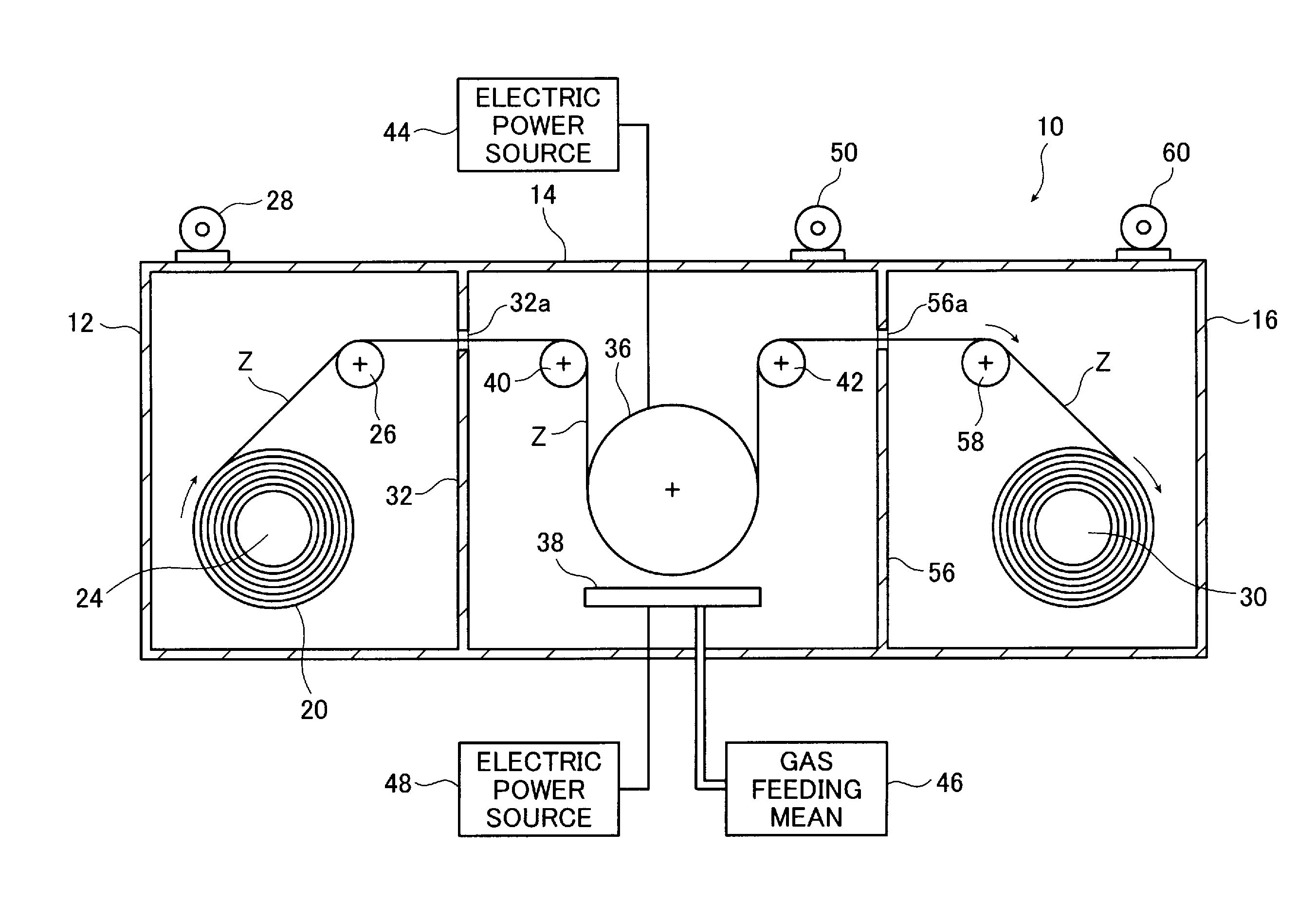
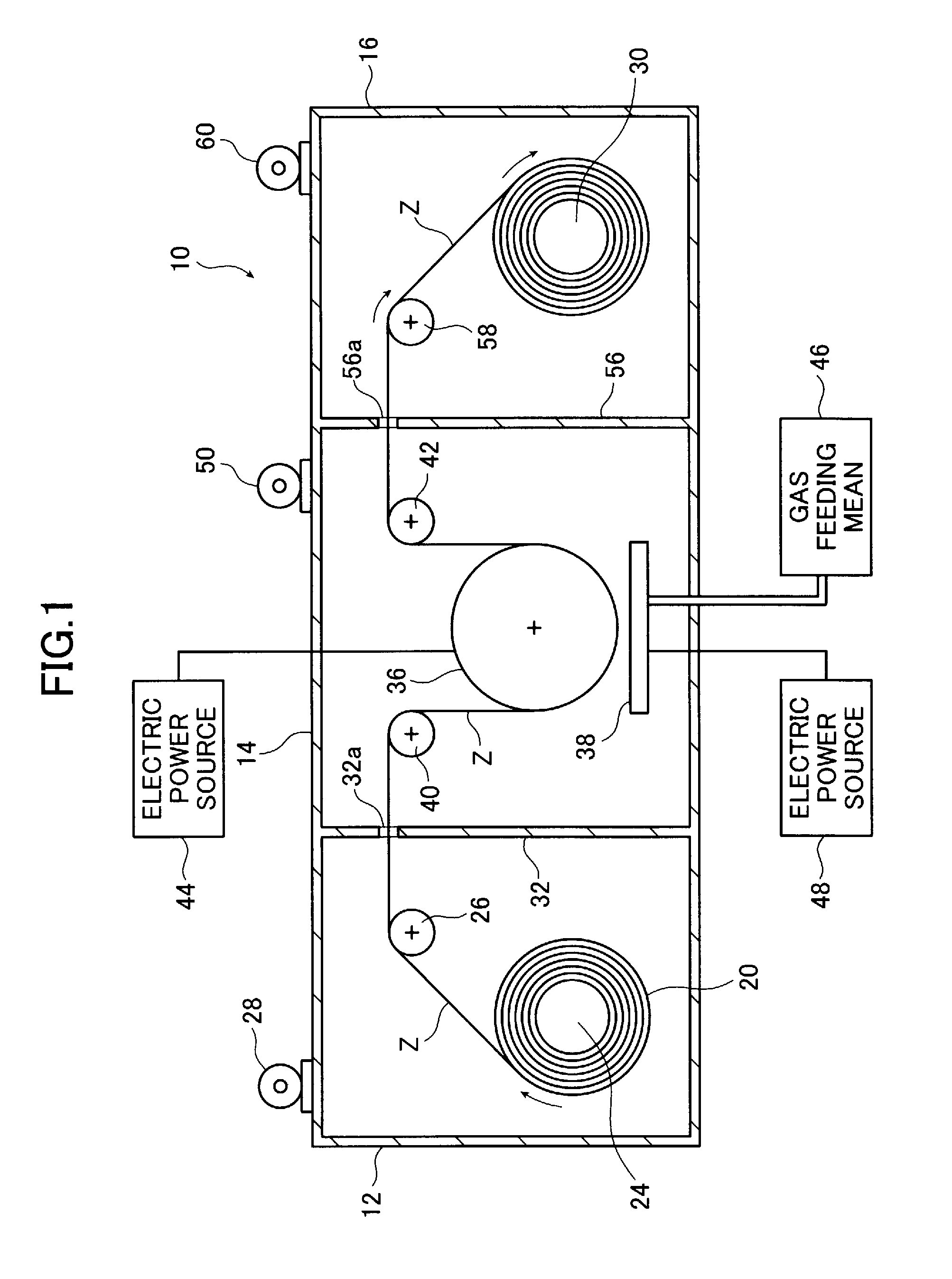
[0108]Using the CVD apparatus 10 as shown in FIG. 1, a 100 nm-thick silicon nitride layer was deposited on the surface of the base film Z to manufacture a gas barrier film.

[0109]A PET film with a thickness of 100 μm (COSMOSHINE A4300, manufactured by Toyobo Co., Ltd.) was used as the base film Z. The portion of the film on which the layer is to be deposited had a length of 1000 m.

[0110]The gaseous raw materials as used were silane gas (SiH4; the flow rate, 50 seem), ammonia gas (NH3; the flow rate, 50 sccm), and nitrogen gas (N2; the flow rate, 400 sccm).

[0111]The drum as used was made of SUS 304 stainless steel as a base material with hard chrome plating, measured 1000 mm in diameter, and had a temperature adjusting means built therein.

[0112]The pressure in the deposition chamber (vacuum chamber) was 40 Pa.

[0113]During deposition, the base film temperature was kept at 70° C. by the temperature adjusting means built in the drum.

[0114]The functional layer as deposited had a thickness...

examples 2 through 5

[0118]A silicon nitride layer was deposited on the surface of the base film Z to manufacture a gas barrier film by following the procedure in Example 1 except that:

[0119]475 W of electric power was supplied from the radio-frequency power source to the showerhead electrode, so that the ratio P / Q was 9.5 W / sccm (Example 2); or

[0120]the deposition pressure was 200 Pa (Example 3); or

[0121]the deposition pressure was 20 Pa (Example 4); or the frequency of the bias potential applied by the bias power source to the drum, that is to say, the frequency of the bias potential applied to the base film Z was 50 kHz (Example 5).


PUM

PropertyMeasurementUnit
temperatureaaaaaaaaaa
pressureaaaaaaaaaa
frequencyaaaaaaaaaa

Abstract

A gas barrier film of high flexibility exhibiting a good gas barrier property over a long period of time is manufactured by a method of manufacturing a gas barrier film by capacitively-coupled plasma CVD using silane gas, ammonia gas, and hydrogen gas and / or nitrogen gas as gaseous raw materials, in which a silicon nitride layer is deposited on a base film at a ratio P / Q of less than 10 [W / sccm], with Q being the silane gas flow rate and P being the plasma-generating electric power, a deposition pressure of 20 to 200 Pa, and at a base film temperature of not more than 70° C. under a bias potential of not more than −100 V applied to the base film.

Description

BACKGROUND OF THE INVENTION[0001]The present invention relates to gas barrier film manufacturing methods utilizing capacitively-coupled plasma CVD.[0002]A resin (plastic) film having a silicon nitride layer deposited on the surface thereof is known as a gas (water vapor) barrier film for a variety of devices, optical elements, and so forth required to be moisture proof.[0003]In this regard, capacitively-coupled plasma CVD (CCP-CVD) is a known process for depositing a silicon nitride layer.[0004]As is well-known, in a method of depositing a layer by CCP-CVD, a pair of electrodes are used between which gaseous raw materials are fed and a voltage is applied to generate plasma, and the plasma causes dissociation or ionization of the gaseous raw materials to make radicals or ions generated, so that a layer is deposited by plasma CVD on the surface of the object to be treated which is placed between the electrodes.[0005]The method by CCP-CVD as above is advantageous in that only a system ...

Claims


Application Information

Patent Timeline
Patent Type & Authority Applications(United States)
IPC IPC(8): H05H1/42
CPCC23C16/345C23C16/545C23C16/4401
Inventor FUJINAMI, TATSUYA
Owner FUJIFILM CORP
Learn More